Pneumatic tire

a pneumatic tire and tire technology, applied in special tyres, non-skid devices, transportation and packaging, etc., can solve the problems of increased tread wear, tire difficulty in manufacturing, and decreased hydroplaning characteristics, so as to optimize worn tire performance, maintain wet performance characteristics of tires, and similar tread performance

Inactive Publication Date: 2007-07-31
THE GOODYEAR TIRE & RUBBER CO
View PDF24 Cites 35 Cited by
  • Summary
  • Abstract
  • Description
  • Claims
  • Application Information

AI Technical Summary

Benefits of technology

[0006]Disclosed herein is a pneumatic tire. The tire is designed to have a variable tread pattern, the tread pattern changing with wear, to achieve similar tread performance for the tire when both new and worn. The changing pattern optimizes the worn tire performance in an attempt to maintain the tire's wet performance characteristics.
[0007]Also disclosed is a pneumatic tire wherein when the tire is a new, or unworn, the tread has a stiff closed design. As the tire is worn, due to the tread configuration and the disclosed invention, the tread is softer with a more open design.
[0023]“Groove” means an elongated void area in a tread that may extend circumferentially or laterally about the tread in a straight curved, or zigzag manner. Circumferentially and laterally extending grooves sometimes have common portions and may be sub classified as “wide”, “narrow”, or “sipe”. A sipe typically is formed by steel blades inserted into a cast or machined mold or tread ring therefore. In the appended drawings, excluding close up drawings, sipes are illustrated by single lines because they are so narrow. A “sipe” is a groove having a width in the range from about 0.2% to 0.8% of the compensated tread width, whereas a “narrow groove” has a width in the range from about 0.8% to 3% of the compensated tread width and a “wide groove” has a width greater than 3% thereof. The “groove width” is equal to tread surface area occupied by a groove or groove portion, the width of which is in question, divided by the length of such groove or groove portion; thus, the groove width is its average width over its length. Grooves, as well as other voids, reduce the stiffness of tread regions in which they are located. Sipes often are used for this purpose, as are laterally extending narrow or wide grooves. Grooves may be of varying depths in a tire. The depth of a groove may vary around the circumference of the tread, or the depth of one groove may be constant but vary from the depth of another groove in the tire.

Problems solved by technology

Hydroplaning characteristics also decrease with increased tread wear due to the reduced groove volume.
However, such a tire is difficult to manufacture due to the necessity of removing the molds that create the submerged grooves.

Method used


Image

  • Pneumatic tire
  • Pneumatic tire
  • Pneumatic tire

Examples


Embodiment Construction

[0041]The following language is of the best presently contemplated mode or modes of carrying out the invention. This description is made for the purpose of illustrating the general principles of the invention and should not be taken in a limiting sense. The scope of the invention is best determined by reference to the appended claims.

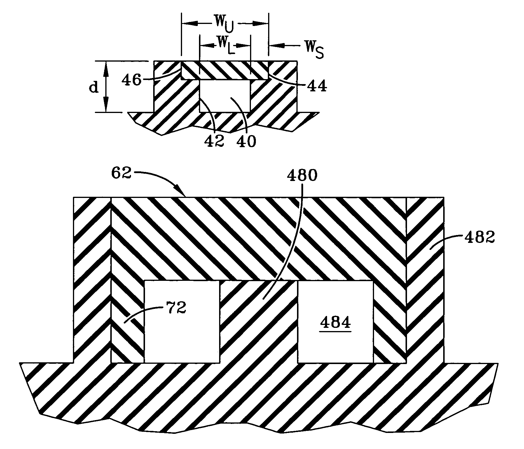
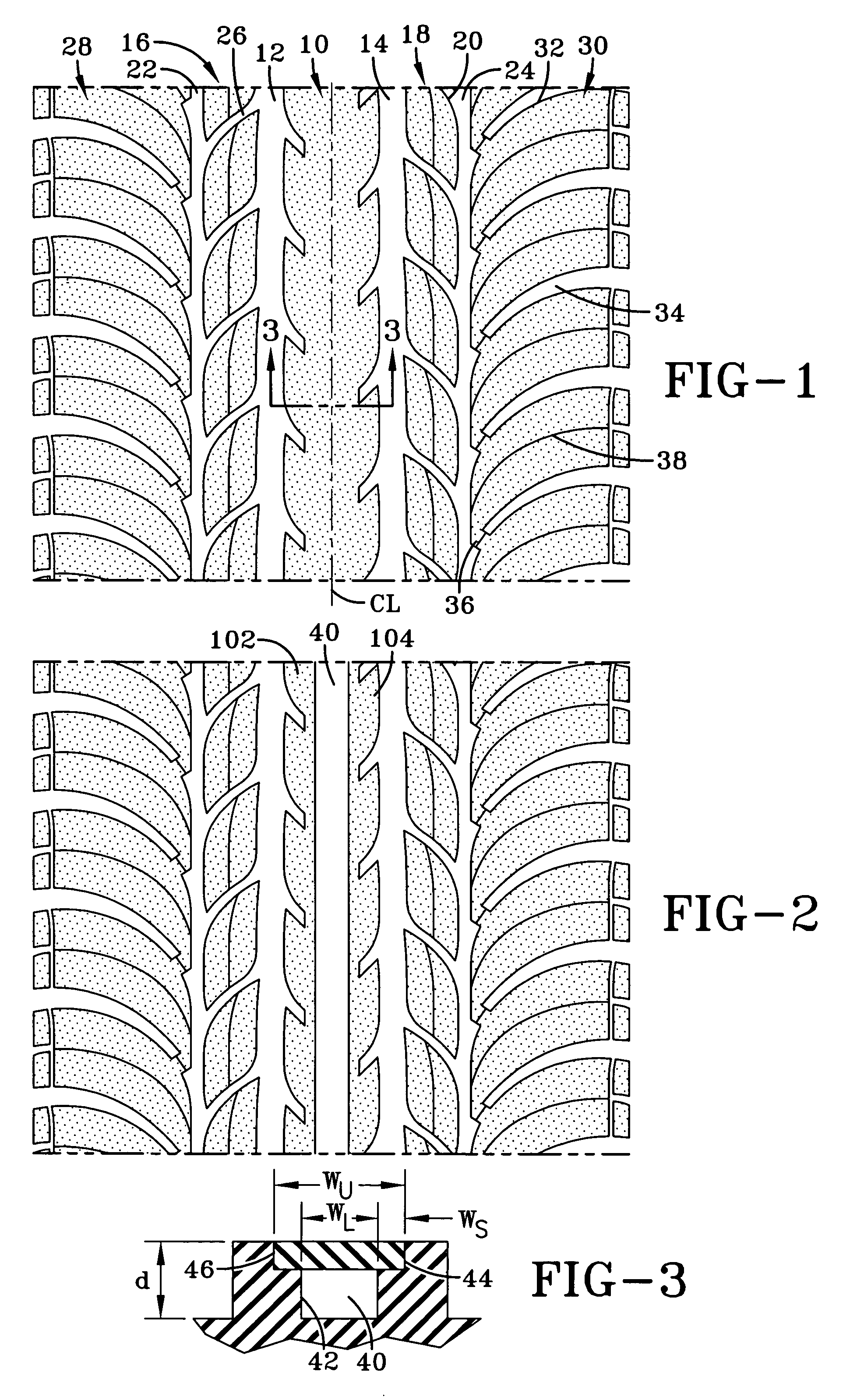
[0042]A tire tread, located on the radially outer surface of a tire, is characteristically defined by a plurality of extending tread elements in the form of blocks and / or ribs. Such tread elements are formed by circumferentially extending and / or laterally extending grooves. In the exemplary tread of FIG. 1, at the unworn stage, the tread is defined by four circumferentially extending grooves, dividing the tread into five rows of tread elements. The tread element row 10 located on the tread centerline CL is a rib defined by circumferential grooves 12, 14. The tread element rows 16, 18 bordering the center tread element row 10 are a plurality of blocks 20...


PUM


Abstract

A tire with a changing tread pattern is formed by first forming a tire having a tread, the tread having at least one circumferential or lateral groove. A wearable filler, having a configuration corresponding to at least a portion of the circumferential or lateral groove formed in the tire, is located in the radially outer portion of the circumferential or lateral groove or a portion of the circumferential or lateral groove, and secured within the grooves so as to create a groove void radially inward of the wearable filler, the void being exposed upon wear of the tire tread.

Description

FIELD OF THE INVENTION[0001]The present invention relates to a pneumatic tire, and more particularly to a tread of a pneumatic tire wherein the tread is configured to provide a different tread pattern as the tire is worn. The invention also discloses method for manufacturing such a tire and tire tread.BACKGROUND OF THE INVENTION[0002]Tire tread patterns are provided with numerous elements such as ribs and blocks, the elements being separated by circumferential and / or transverse grooves. The grooves provide means for water evacuation and form the biting edges of the tread elements.[0003]When a tire is new, the tread has a maximum tread height. This initial height may vary depending upon the intended use of the tire; a winter tire has an increased tread depth in comparison to an all season tire. Regardless of the initial tread depth, when the tire is new, the tread elements have an initial stiffness. The actual stiffness of the tread elements is dictated by the block size, shape, and ...

Claims


Application Information

Patent Timeline
Patent Type & Authority Patents(United States)
IPC IPC(8): B60C11/03B60C11/117B60C11/24
CPCB60C11/0302B60C11/0323B60C11/13Y10T152/10027B60C11/00B60C11/03
Inventor CROISSANT, BERNARDJACQUE, CLAUDEROESGEN, ALAIN EMILE FRANCOISROCH, PETER PHELPSWEYDERT, MARCGINTER, MARC ERNESTWEIMER, ANDREW FREDERICKNGUYEN, GIA VANCAMBRON, ANNE-FRANCE GABRIELLE JEANNE-MARIE
Owner THE GOODYEAR TIRE & RUBBER CO
Why Eureka
Try Eureka