Fuel injector with hydraulic flow control

a technology of fuel injector and hydraulic flow control, which is applied in the direction of fuel injecting pumps, machines/engines, mechanical equipment, etc., can solve the problem of relatively slow pressure increas

Inactive Publication Date: 2007-07-31
STANDYNE INC
View PDF12 Cites 11 Cited by
  • Summary
  • Abstract
  • Description
  • Claims
  • Application Information

AI Technical Summary

Benefits of technology

[0010]At higher engine speeds, the pressure of the high pressure pulse increases more rapidly, thereby giving the initial hydraulic pressure wave sufficient energy to move the valve through the mid-range of valve travel to open the primary fuel flow path. As a result, pilot injection is typically more pronounced at lower engine speeds with frequently only a change to the injection rate shape occurring at higher speeds.

Problems solved by technology

At idle and low engine speeds, pressure increases relatively slowly with time so that an initial hydraulic pressure wave through the pilot fuel flow path does not have sufficient energy to move the needle valve through the mid-range of valve travel to open the primary fuel flow path.

Method used


Image

  • Fuel injector with hydraulic flow control
  • Fuel injector with hydraulic flow control
  • Fuel injector with hydraulic flow control

Examples


Embodiment Construction

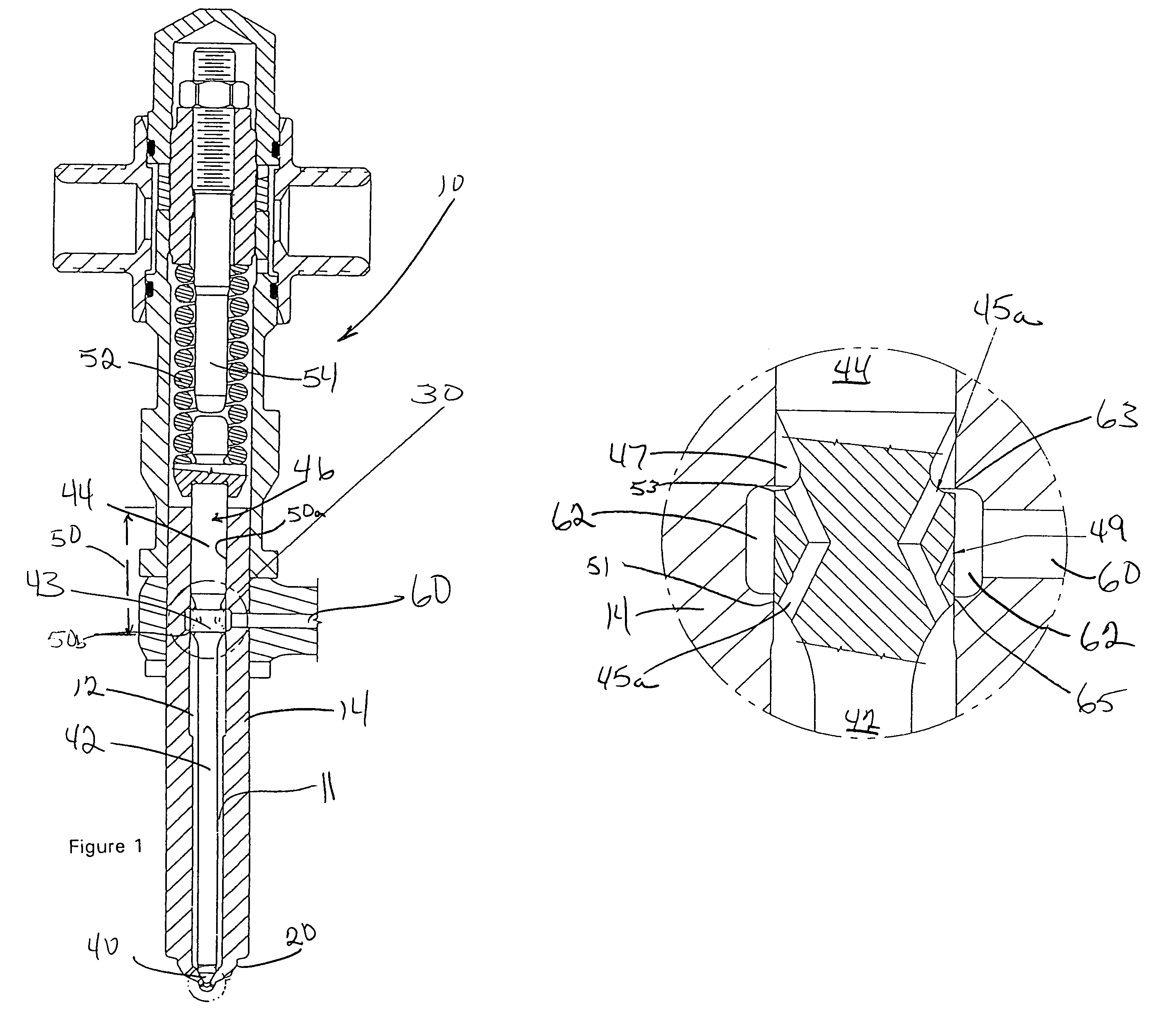
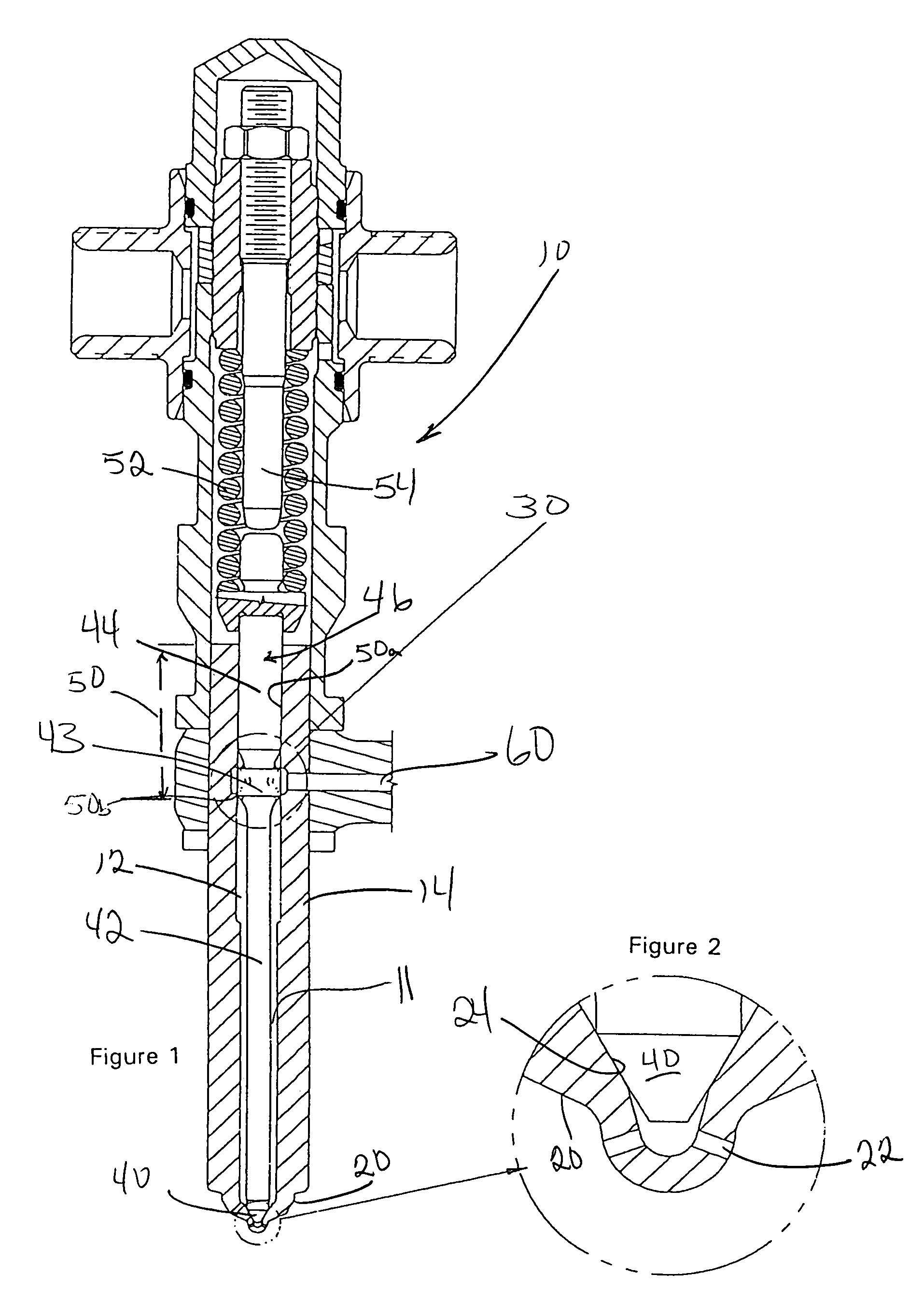
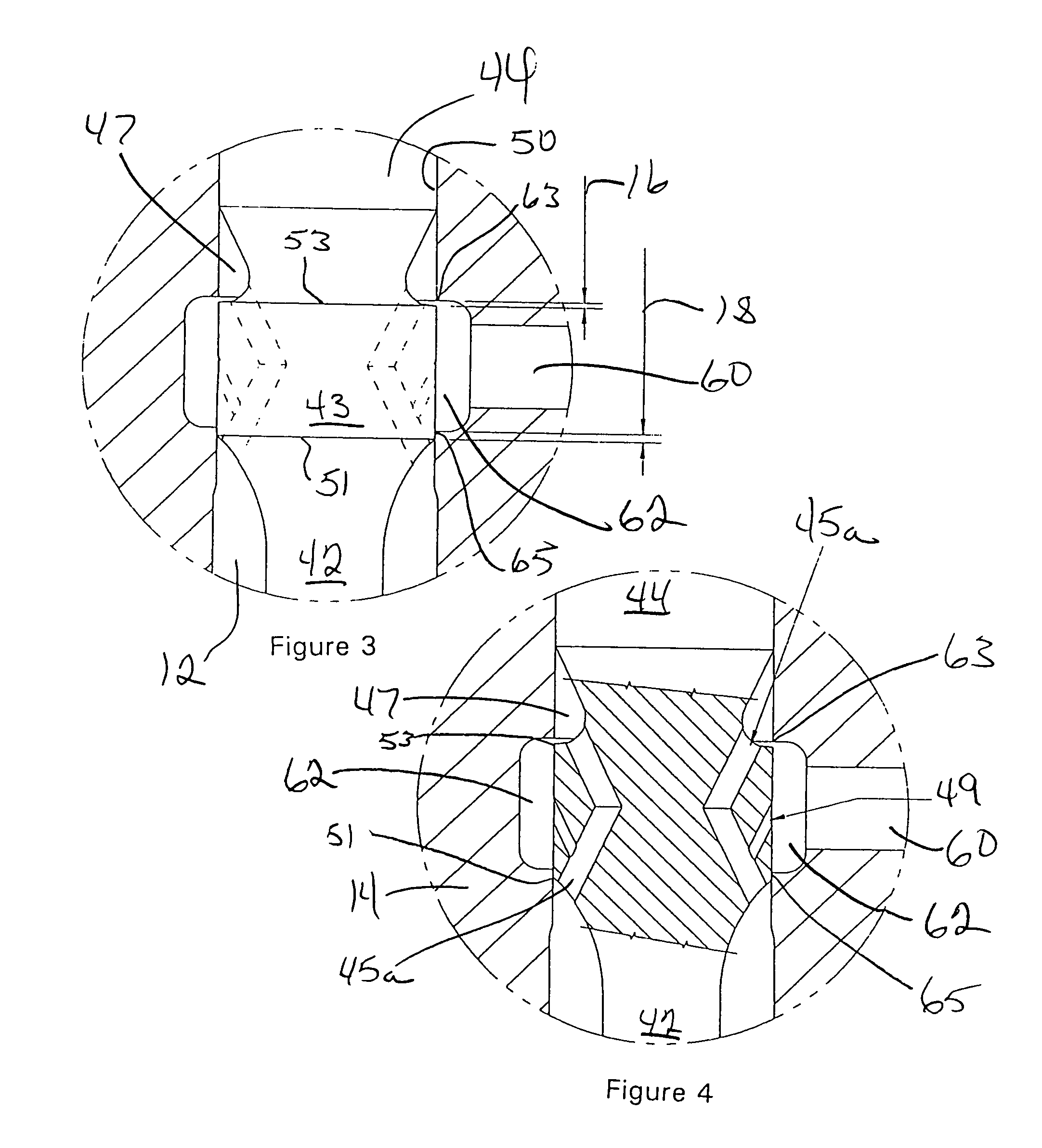
[0019]With reference to the drawings wherein like numerals represent like parts throughout the figures, a fuel injector incorporating a hydraulic flow control 30 according to aspects of the present invention is generally designated by the numeral 10. In general structure and function, the fuel injector 10 is of the type in which an nozzle holder body 14 defines a needle bore 11 extending between a nozzle seat 24 and a needle guide 50. A nozzle body 20 encloses one end of the needle bore 11 and defines spray holes 22 through which fuel is injected. A needle valve 46 is received in the needle bore 11 for axial reciprocation therein between a closed position (shown in FIG. 1) and an open position. A needle valve shank 42 connects the needle valve head 44 to the needle valve tip 40. The needle valve 46 is biased toward the closed position by a pressure adjusting spring 52. A needle lift adjusting screw 54 defines the axial travel the needle valve 46 is permitted between its closed and o...


PUM


Abstract

A fuel injector incorporates a flow control into the needle valve and valve body to regulate fuel flow through the injector. The flow control defines an initial pilot fuel flow path that is closed by needle valve movement away from the nozzle seat. A primary fuel flow path requires axial movement of the needle valve through a mid-range position in which neither fuel flow paths are open. At low engine speeds, the needle valve is not driven through its mid-range position and closes prior to being driven to its fully open position, resulting in a pilot injection. At higher engine speeds, the needle valve is driven through its mid-range position eliminating a distinct pilot injection to provide only rate shaping.

Description

FIELD OF THE INVENTION[0001]The present invention relates generally to fuel injectors, and more particularly to fuel injectors configured to regulate the rate of fuel injection.BACKGROUND OF THE INVENTION[0002]Motor vehicles are required to comply with increasingly stringent limits on noise and emissions imposed by federal, state, and local regulatory bodies. Since published research has demonstrated noise and emissions from an internal combustion engine are influenced by the time history of the fuel flow rate through the injector spray holes, or injection rate shape, considerable effort has been expended to adjust and control the shape of this injection flow rate curve in response to the specific requirements of a particular engine application. Most hydraulic methods of regulating the flow rate at the injector involve either the use of a partial restriction or alternate flow path upstream from the nozzle spray holes to regulate the amount of fuel to reach the exit of the injector. ...

Claims


Application Information

Patent Timeline
Patent Type & Authority Patents(United States)
IPC IPC(8): F02M61/20F02M45/08F02M47/02F02M47/06F02M61/04
CPCF02M45/08F02M47/06F02M61/042
Inventor CIBOTTI, GLEN J.
Owner STANDYNE INC
Why Eureka
Try Eureka