Hybrid fuel injection system

a fuel injection system and hybrid technology, applied in the direction of fuel injecting pumps, electric control, machines/engines, etc., can solve the problems of/or injection pressure control and pressure level, inability to provide split injections, and inability to generate adequate high injection pressure, etc., to achieve selective rate shaping and multiplicity of injections

Inactive Publication Date: 2006-07-18
ELECTRO-MOTIVE DIESEL
View PDF11 Cites 8 Cited by
  • Summary
  • Abstract
  • Description
  • Claims
  • Application Information

AI Technical Summary

Benefits of technology

[0008]The present invention is a hybrid fuel injection system which allows electronic control over th

Problems solved by technology

It is impossible to provide split injections and/or injection pressure control and pressure level.
At engine idle and lower speeds, the UPS cannot generate adequate high injection pressures that are necessary to achieve complete combustion.
However, it cannot provide split injections that are essential to reduce certain exhaust emissions, engine noise, and improve fuel efficiency.
However, the high pressure CRS allows only controlling simple and multiple inje

Method used


Image

  • Hybrid fuel injection system
  • Hybrid fuel injection system
  • Hybrid fuel injection system

Examples


first embodiment

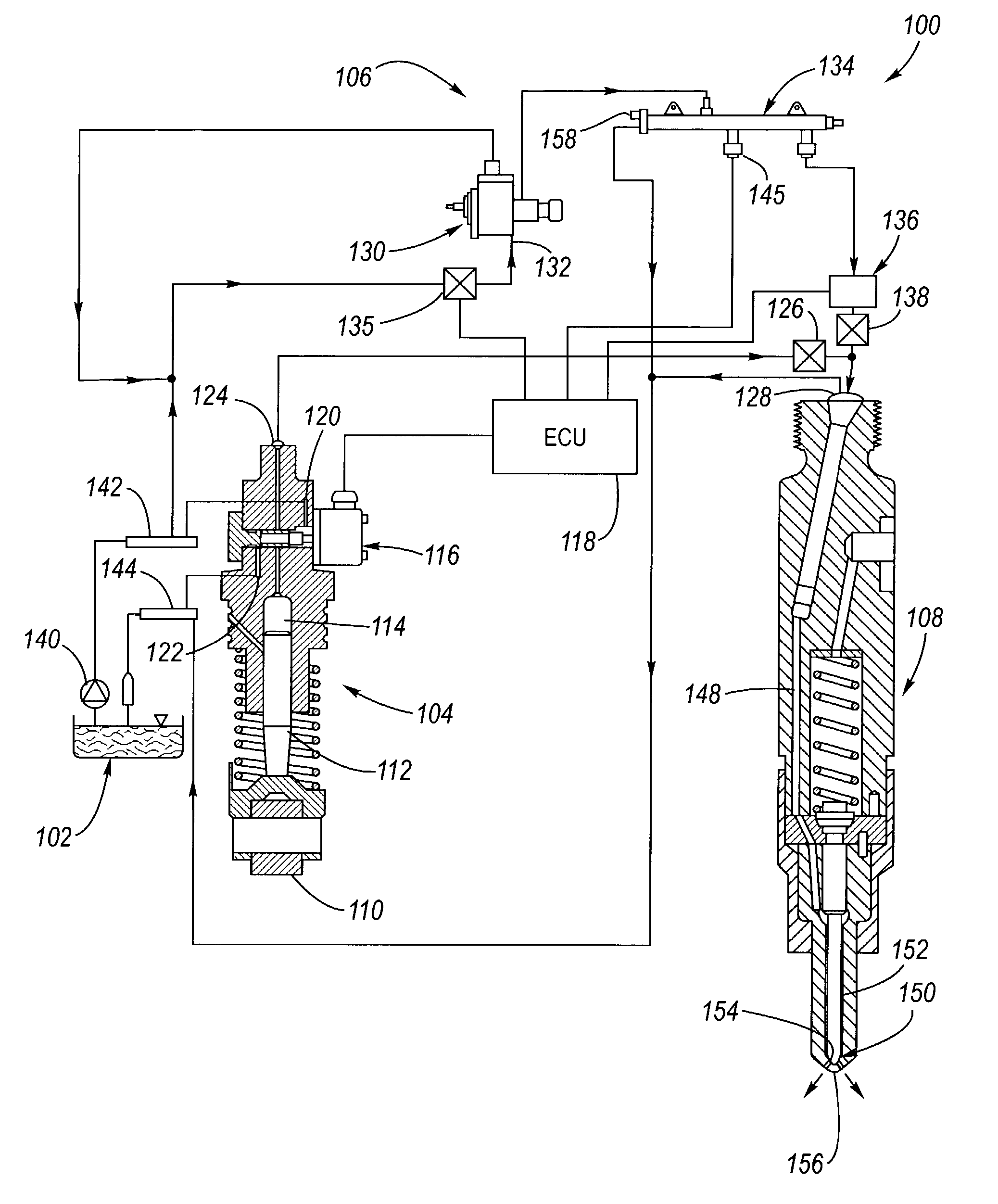
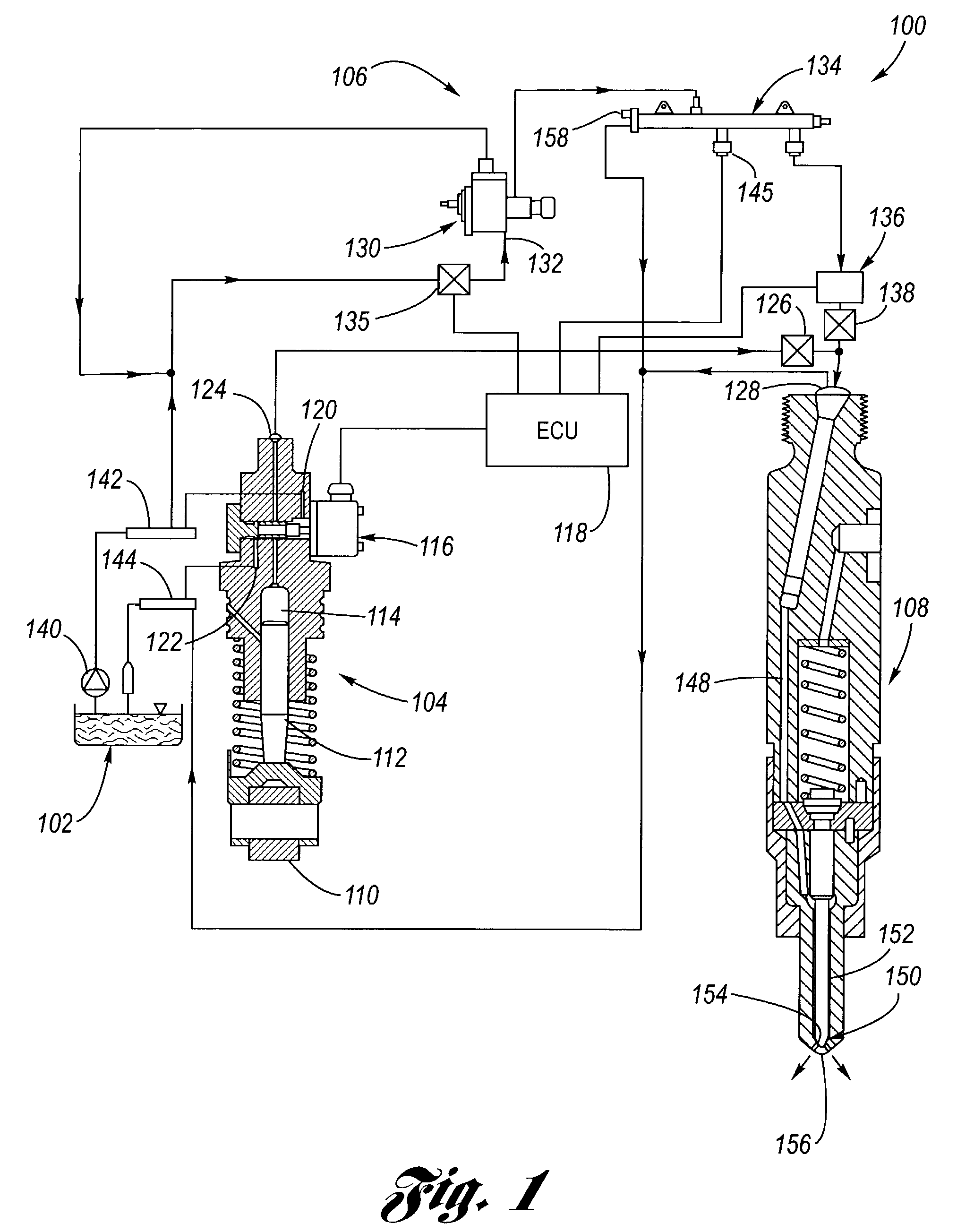
[0020]Referring now to the drawing, FIG. 1 depicts the hybrid fuel injection system 100 according to the present invention. A fuel tank 102 supplies fuel via various fuel lines to both a unit pump system (UPS) 104 and a common rail system (CRS) 106. The outputs of the UPS 104 and the CRS 106 are input to a fuel injector 108. In this regard, there is one UPS respectively for each fuel injector, and the CRS is common to all fuel injectors.

[0021]Each UPS 104 provides the main fuel injection to its respective fuel injector 108. The UPS is of common construction, including, for example a cam roller follower 110 for following a cam 115, a plunger 112, a pumping space 114, a pump solenoid valve 116 operatively connected to an electronic control unit (ECU) 118, a fuel inlet 120, a leakage fuel drain 122 and a pressurized fuel outlet 124 which is connected via tubing to a UPS check valve 126, which, in turn, communicates with the fuel input 128 of the fuel injector 108.

[0022]The CRS 106 incl...

second embodiment

[0027]Referring now additionally to FIGS. 3 and 4, the hybrid fuel injection system 100″ according to the present invention will be detailed. In this regard, the unit pump system 104, the common rail system 106 and the ECU 118 as discussed hereinabove with respect to FIGS. 1 and 2 are utilized.

[0028]Now, the fuel injector 108″ has an injector passage 148′ which only communicates with the UPS 104. The CRS 106 is connected via tubing to a CRS solenoid valve 136′ and then via tubing 160 to a port 162 in the fuel injector 108″. The port 162 communicates with a sac 164 via a passageway 166 internal to the fuel injector 108″. The CRS solenoid valve 136′ is operated under command from the ECU 118.

[0029]Operationally, the UPS 104 supplies the major fuel injection event, and the CRS 106 supplies one or more auxiliary fuel injections which may precede, coincide with, or follow the main injection event of the UPS. Accordingly, the rate shape of the main fuel injection event may be electronical...


PUM


Abstract

A hybrid fuel injection system which allows electronic control over the injection processes, wherein selective rate shaping and multiplicity of injections is possible. The hybrid fuel injection system consists of an add-on common rail system (CRS) which provides supplemental fuel injections with respect to the main fuel injections provided by a unit pump system (UPS). Additionally, the CRS can serve to provide fuel injections as necessary to effect a “limp-home” mode of engine operation in the event of a failure of the UPS. Both the CRS and the UPS use common fuel supply, return, injector, and electronic controller.

Description

TECHNICAL FIELD[0001]The present invention relates to fuel injection systems for internal combustion engines, particularly diesel engines. More particularly, the present invention relates to an electronically-controlled hybrid fuel injection system for providing selective fuel injection rate shaping and multiplicity of injections.BACKGROUND OF THE INVENTION[0002]To meet future EPA emissions standards, large bore medium speed diesel engines need greater flexibility and reliability on the fuel injection equipment with regard to fuel metering, injection timing, injection pressure, rate of injection (rate shaping) and multiple (pre-, post-, or split) injections independent of engine speed. A production unit pump system (UPS) offers the advantage of design simplicity with flexibility on electronically-controlled injection timing.[0003]However, the rate of injection and injection pressure are solely dependent upon cam profile and engine speed, and are optimized for full load operating con...

Claims


Application Information

Patent Timeline
IPC IPC(8): F02B3/00F02D41/22F02D41/38F02D41/40F02M45/02F02M57/02F02M59/36F02M61/18F02M63/00F02M63/02
CPCF02D41/22F02D41/3809F02M45/02F02M63/0225F02M59/366F02M61/18F02M63/0007F02M63/0205F02M57/02F02D41/402F02D2400/11
Inventor POOLA, RAMESH B.LILL, RICHARD J.GOTTEMOLLER, PAULGOETZKE, MICHAEL B.
Owner ELECTRO-MOTIVE DIESEL
Why Eureka
Try Eureka