Valve assembly having multiple rate shaping capabilities and fuel injector using same

a technology of fuel injector and valve assembly, which is applied in the direction of fuel injecting pump, machine/engine, operating means/releasing devices of valve, etc., can solve the problem of not being able to produce some front-end rate shapes

Inactive Publication Date: 2005-08-30
CATERPILLAR INC
View PDF10 Cites 8 Cited by
  • Summary
  • Abstract
  • Description
  • Claims
  • Application Information

AI Technical Summary

Benefits of technology

[0007]In yet another aspect of the present invention, a method of injecting fuel includes a step of relieving pressure on a closing hydraulic surface of a needle valve member at least in part by energizing an electrical actuator with current above a first threshold level. Fuel is then directed to a nozzle outlet via a restricted passage and an unrestricted passage at least in part by energizing the electrical actuator with a higher current that is above a second threshold level.

Problems solved by technology

While a number of fuel injectors have been developed that have limited rate shaping capabilities, the ability to produce some front end rate shapes has not been possible.

Method used


Image

  • Valve assembly having multiple rate shaping capabilities and fuel injector using same
  • Valve assembly having multiple rate shaping capabilities and fuel injector using same
  • Valve assembly having multiple rate shaping capabilities and fuel injector using same

Examples


Embodiment Construction

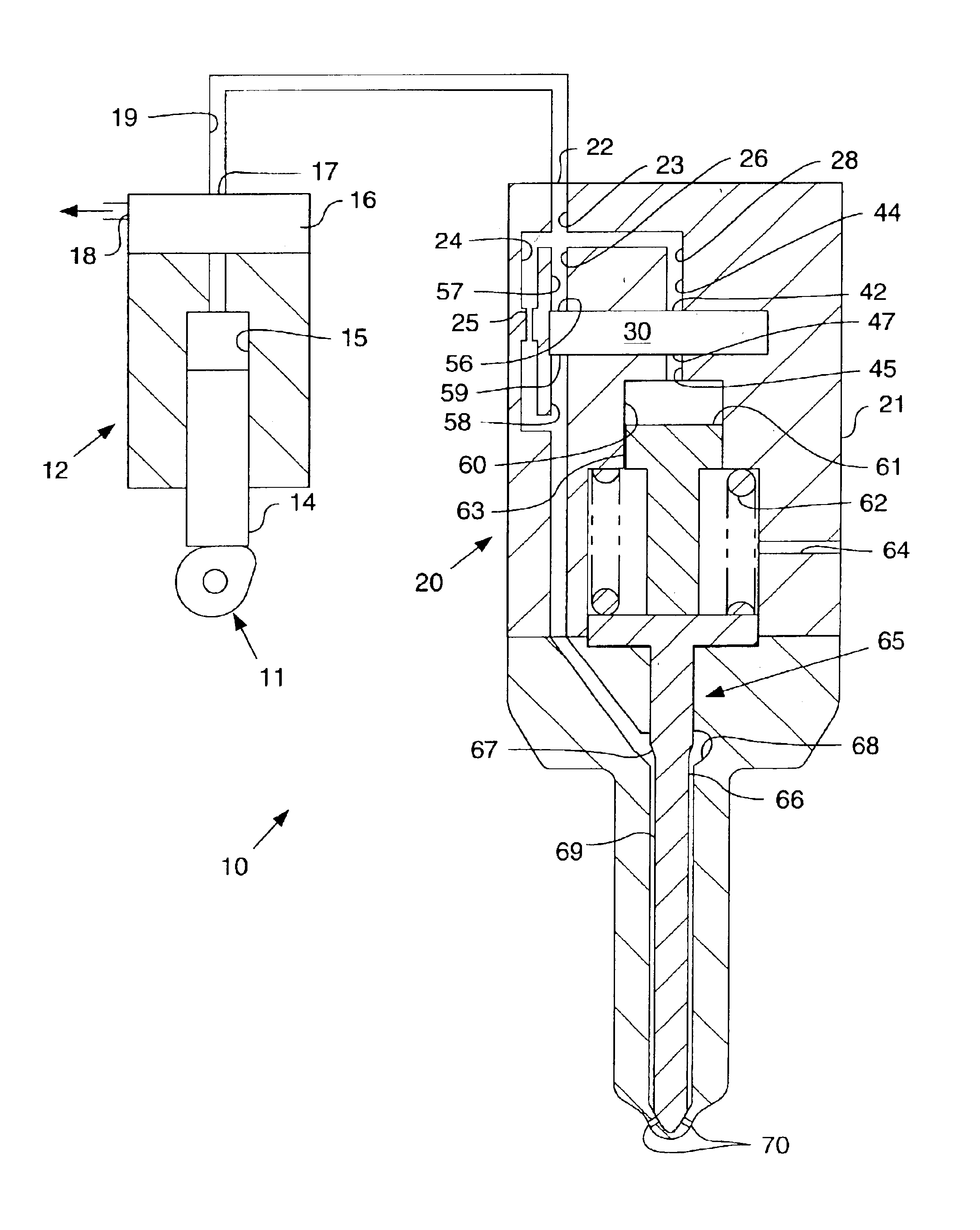
[0014]Referring now to FIG. 1, there is illustrated a fuel injection system 10 that includes a fuel pressurizer that provides a reciprocating plunger 14. Reciprocating plunger 14 defines a portion of a fuel pressurization chamber 15. As illustrated in FIG. 1, the fuel pressurizer is preferably a unit pump 12 that supplies pressurized fuel to one or more fuel injectors 20 and is separated from the one or more fuel injectors 20. Unit pump 12 includes a plunger 14 that is moved to reciprocate between an advanced position and a retracted position by the rotation of a cam 11. Unit pump 12 preferably includes a conventional electronically controlled spill valve 16 which typically has two positions. When spill valve 16 is in its first, open position, low pressure fuel is spilled from a fuel pressurization chamber 15 to a pump inlet / spill port 18 for recirculation. When plunger 14 is undergoing its pumping stroke and spill valve 16 is in its second, closed position, fuel in fuel pressurizat...


PUM


Abstract

Engineers have determined that the performance of fuel injectors, including those used in common rail fuel injection systems, can be increased, and undesirable emissions reduced, by controlling the mass flow rate of fuel injected into a combustion chamber during an injection event. While a number of fuel injectors have been developed that have limited rate shaping capabilities, the ability to produce some front end rate shapes has not been possible. In an effort to increase rate shaping capabilities, the present invention includes a valve assembly having at least one valve member that is movable between a plurality of positions to control fluid communication between a number of fluid inlets and outlets.

Description

TECHNICAL FIELD[0001]This invention relates generally to valve assemblies, and more particularly to rate shaping valve assemblies for fuel injectors.BACKGROUND[0002]Electronically controlled fuel injection systems are becoming more widespread for use with diesel engines. One example of such a system is the amplifier piston common rail system (APCRS) illustrated in the paper “Heavy Duty Diesel Engines—The Potential of Injection Rate Shaping for Optimizing Emissions and Fuel Consumption”, presented by Messrs. Bernd Mahr, Manfred Durnholz, Wilhelm Polach, and Hermann Grieshaber; Robert Bosch GmbH, Stuttgart, Germany, at the 21st International Engine Symposium, May 4-5, 2000, Vienna, Austria. In the Bosch fuel injection system, a controlled leakage strategy is utilized to control opening and closing of the needle. For instance, for pre-injection and the first portion of a main injection having a boot rate trace, fuel is directed along a by-pass route. After the main injection has begun,...

Claims


Application Information

Patent Timeline
Patent Type & Authority Patents(United States)
IPC IPC(8): F02M59/00F02M59/46F02M63/00F02M45/08F16K31/06F16K31/36F16K31/383F02M45/00
CPCF02M45/08F02M47/02F02M47/043F02M63/0007F02M63/0017F02M63/0047F02M63/0061F16K31/0624F16K31/0634F16K31/383
Inventor AZAM, JUNRUGILLIS, EDWARD R.
Owner CATERPILLAR INC
Why Eureka
Try Eureka