Detectable warning-dots demarkation for pedestrian safety

a pedestrian and detection technology, applied in road signs, roads, constructions, etc., can solve problems such as not necessarily smoothly circular in plan-view, and achieve the effects of enhancing tenacity, improving pedestrian foot traction, and promoting bonding strength

Active Publication Date: 2007-07-31
HYAMS CHRISTOPHER A
View PDF23 Cites 36 Cited by
  • Summary
  • Abstract
  • Description
  • Claims
  • Application Information

AI Technical Summary

Benefits of technology

[0014]Additionally, it is preferred that the apex portion be embossed with a centered X-shaped channel, serving to provide improved pedestrian foot traction when stepped upon. While it is preferred that my safety-button device be generally installed in a geometric format having a regular installed center-to-center spacing interval of about 1⅝″ (measured linearly) or 2⅜″ (measured diagonally);—it nevertheless is understood that various other sorts of geometric patterns may be resorted to as well.
[0015]Another important feature of my safety-button device, is the provision of an improved bottom-side surface, to enhance the tenacity by which the safety-button holds to the surface of an existing walkway. One option is to coarse-sandblast the cavity portion of the female-die in which my plastic safety-button is molded, thereby transfering the texture to the bottom-surface of the injection-molded piece. However, in order to negate any thus resulting skin-like sheen, it is ultimately preferred that the safety-button itself be directly sandblasted post-molded, as to thereby present the best attainable “tooth” to which the subsequently applied intermediate substrate bonding-agent can adhere; and hence, thereby promote greater bonding-strength between the safety-button relative to the pavement. Yet another optional approach toward attaining a permanently fixed attachment to the walkway pavement surface, is to prepare the die-mold with a raised-embossment in the form of concentric circles, which also preferably includes a centrally superimposed X-formation; which results in a finished part having the identical formations in reverse relief. The bottom-side of the molded safety-button would thus exhibit a series of concentric circular channels in combination with the X-formation; the latter portion of the channeling thereby serving to actually vent-off any air or surplus bonding-agent prior to the bonding-agent curing into a hard substrate.
[0016]An alternate embodiment for the safety-button's bottom-side, is to employ an annular-boss proximal the perimeter of the safety-button, the annular-boss necessarily employing an angled-undercut ledge forming a slight annular-declivity into which the bonding-agent substrate can migrate while curing;—thereby achieving a positive mechanical retention of the safety-button relative to the supporting pavement. This ledge need be only approximately 1 / 16″-deep, so an annular-declivity having an approximate 30-degree undercut, would be easily extracted from the female-die while the post-molded cooling part is still semi-moltant, and therefore sufficiently compliant as to yield to the extraction process popping the part out of the female-die to be ready for the next rapid cycling of the injection-molding procedure. Here, it is also preferred that the annular-boss be provided with three equidistantly spaced apart radial-slots, whereby excess bonding-agent can ooze and any captive air can readily vent from beneath the walkway-pavement installed safety-button prior to catylized-hardening of the bonding-agent.
[0017]Another iteration option of safety-button is configuring the bottom-side with a concavity into which the bonding-agent substrate can flow during installation upon the walkway-pavement, which has been discovered to provide a slightly more compliant, and hence softer harmonic tonal-quality when tapped with a blind person's guide-cane. This tonal characteristic, while considered desirable by the ADA to enhance detection by cane-tip, is not a requsite criteria. An uppermost venting-port can also be included in this version of my safety-button, through which excess premixed fluid bonding-agent can spew; thereby eliminating any entrapped-air.

Problems solved by technology

Hence, the shape of my truncated-dome detectable-warning device can even be a pyramid like shape, therefore not necessarily smoothly circular in plan-view.

Method used


Image

  • Detectable warning-dots demarkation for pedestrian safety
  • Detectable warning-dots demarkation for pedestrian safety
  • Detectable warning-dots demarkation for pedestrian safety

Examples


Embodiment Construction

[0021]The foregoing and still other objects of this invention will become fully apparent, along with various advantages and features of novelty residing in the present embodiments, from study of the following description of the generic species embodiments and study of the ensuing description of these embodiments. Wherein indicia of reference are shown to match a particular feature stated in the text, as well as the claims section annexed hereto; and accordingly, a better understanding of the invention and the variant uses is intended, by reference to the drawings, which are considered as primarily exemplary and not to be therefore construed as restrictive in nature; wherein:

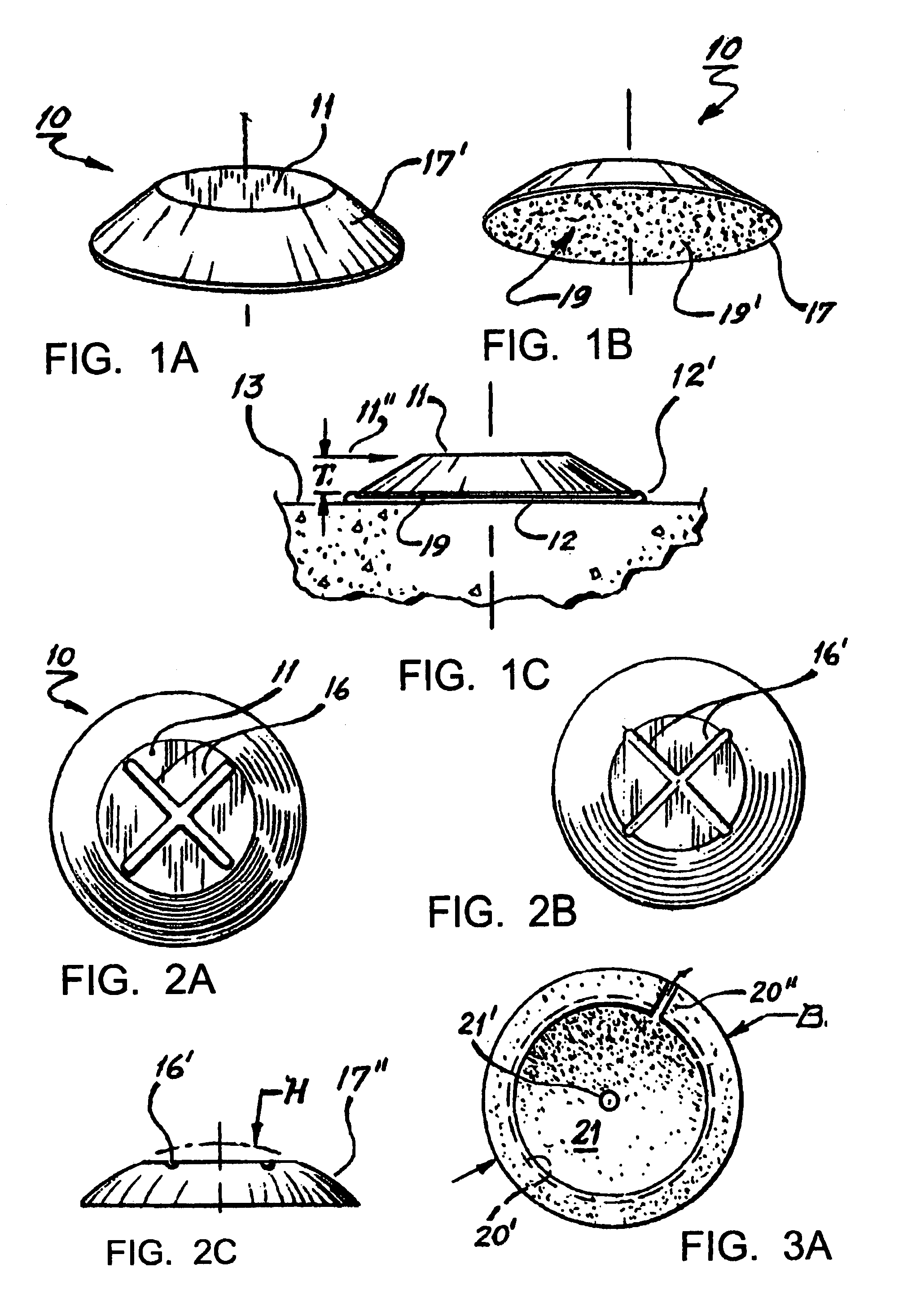
[0022]FIG. 1A, is an pictorial-view favoring the top of my basic safety-button device;

[0023]FIG. 1B, is a lower-oblique pictorial-view showing the bottom side thereof;

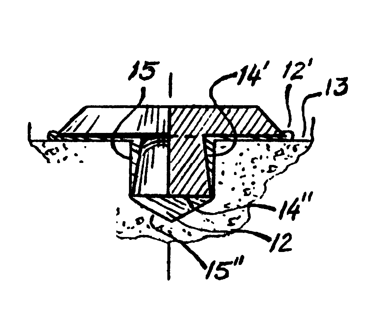
[0024]FIG. 1C, is a side / elevation-view thereof;

[0025]FIG. 2A, is a top / plan-view thereof, showing an anti-slip provision;

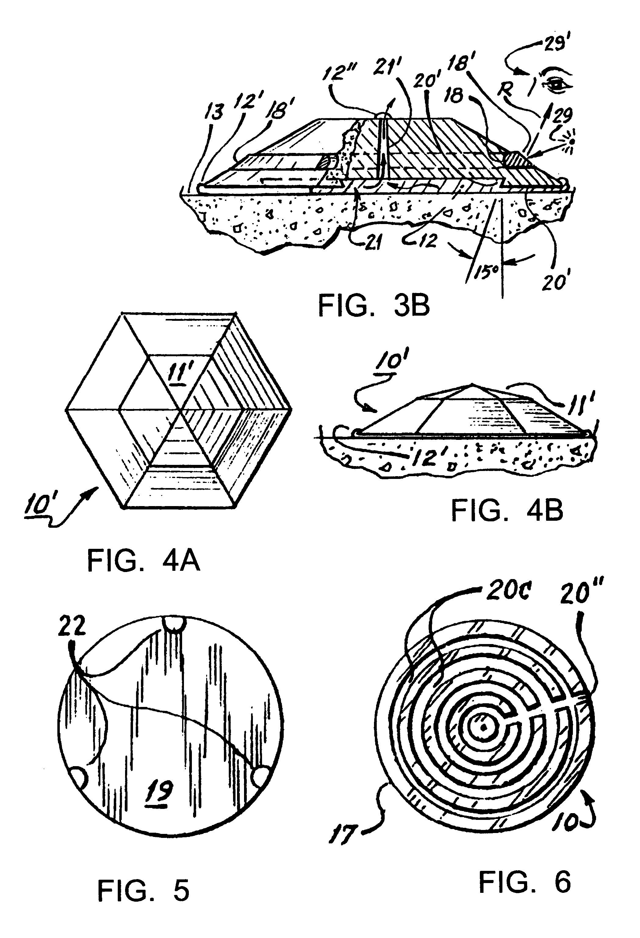
[0026]FIG. 2B, is a alter...


PUM


Abstract

A novel small quasi-hemispherical truncated-dome modular-dot like device, which can be readily affixed to pavement in a Federally-mandated pattern via a special hole / matrix-stencil;—the resulting demarkations thereby serving to alert the Legally-blind (as well as Guide-dogs, persons in wheelchairs, and otherwise pre-occupied non-handicapped individuals) their pedestrian-pathway is entering into a potentially dangerous transition area typically crossed by a motor-vehicle pathway. The individual so called DW-DOTS™ are resilient circular low-profile devices having an annular-ramp configuration, and thus standing out only sufficiently above a foot-surface as to enable foot-tactile detection, yet not pose the potential tripping hazzard known to embedded-mats. This novel safety-button offers a desired permanent contrasting-color, plus has a definition and rugged permanency not known to poured-dot installations. The disclosure sets forth various generic-variant structural embodiments, as well as the preferred method of attachment to a walkway-pavement surface.

Description

BACKGROUND OF THE INVENTION[0001]1. Field of Invention[0002]This invention relates to device and method for guiding the visually-impaired pedestrian relative to danger-zones such as vehicular crossings proximal paved walkways; and more specifically, it relates to those types of apparatus devised with raised foot-tactile demarcations.[0003]2. Background History[0004]With increased awareness as to the need for improved safety precautions for the estimated 12-million persons having varying degrees of disabling sight impairment, on 26Jul. 1991, the U.S.Congress published federally legislated Regulation—US / CFR-Parts: 35 & 36 (Re: gov.structures & pvt.structures respectively) regarding actual implementation of truncated-domes, which regulation was ushered in by the U.S. Justice Dept. via their truncated-domes, which regulation was ushered in by the U.S. Justice Dept. via their ADA / Americans w / Disabilities Act Dept. (Re: tech.info: www.access-board.gov);-however the Fed.DOT / Dept.-Of-Transp...

Claims


Application Information

Patent Timeline
Patent Type & Authority Patents(United States)
IPC IPC(8): E01F9/06E01F9/04E01F9/053
CPCE01C19/44E01C23/0993E01F9/042E01F9/512
Inventor HYAMS, CHRISTOPHER A.
Owner HYAMS CHRISTOPHER A
Why Eureka
Try Eureka