Electric switch, especially a piezo switch, with optical and/or mechanical feedback of the switching operation

a piezo switch and switching operation technology, applied in the field of piezo switches, can solve the problems of unimpressive illumination of the actuation face, increased material and assembly costs, and reduced light yield through light absorption

Inactive Publication Date: 2007-07-31
DYNA SYST
View PDF26 Cites 3 Cited by
  • Summary
  • Abstract
  • Description
  • Claims
  • Application Information

AI Technical Summary

Benefits of technology

[0023]Since only the three dimensionally milled-out symbol body is visible from the front of the cover plate, this symbol body serves simultaneously as an actuation surface for the switch. This symbol body is illuminated according to the invention.

Problems solved by technology

Of disadvantage herein is that for the actuation of the switch several different elements expensive of production and at least partially transparent (operating element with symbol field and light guide element with oblique surface) must be provided, which leads to increased material and assembl

Method used


Image

  • Electric switch, especially a piezo switch, with optical and/or mechanical feedback of the switching operation
  • Electric switch, especially a piezo switch, with optical and/or mechanical feedback of the switching operation
  • Electric switch, especially a piezo switch, with optical and/or mechanical feedback of the switching operation

Examples


Embodiment Construction

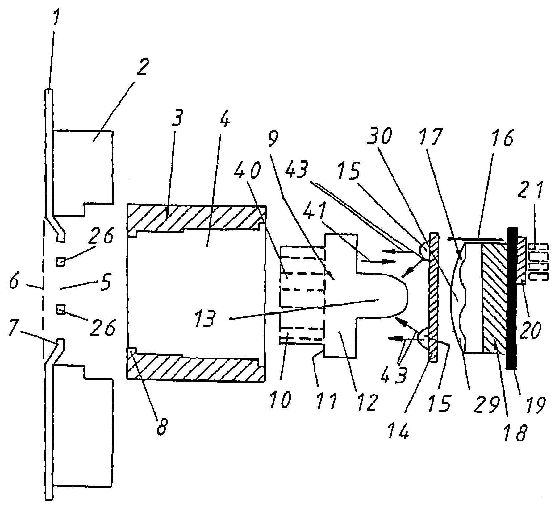
[0062]The piezo switch according to the invention according to FIG. 1 resides behind a cover plate 1, which can be formed of any desired material, for example of wood, metal, glass or synthetic material. The cover plate 1 can be formed in any desired manner.

[0063]For the mechanical stabilization of the cover plate it can be backed with a support 2 which is comprised for example of a synthetic material. The support 2 can herein be adhered on the cover plate 1. But it can also be connected with the cover plate 1 integrally with the material.

[0064]The support 2 can also be clamped mechanically on the cover plate 1, with corresponding clamp brackets being available which are not further shown.

[0065]In the cover plate 1 a cutout 5 is disposed, with the cutout 5 being offset back from the fronting side front face 6 and forming a back-offset 7.

[0066]On support 2 is fastened the housing 3 of a piezo switch and it is possible to employ any fastening means. The housing can herein be clamped, ...


PUM


Abstract

The invention relates to an electric switch, especially a piezo switch, with optical and/or mechanical feedback of the switching operation. The switch contains at least one switching element, especially beneath a cover panel, which can be activated by means of an activating element. This causes a switching signal to be generated and guided out via electrical contacts. The activating element itself is configured in the form of a passive luminous body consisting of an at least translucent material, which can be illuminated by active luminous means. The mechanical feedback of the switching operation can take place using a vibrator which is activated by the switching operation that has been initiated and conveys a vibrating motion to the luminous body.

Description

BACKGROUND OF THE INVENTION[0001]1. Field of the Invention[0002]The invention relates to an electric switch, in particular a piezo switch, with optical and / or mechanical feedback of the switching operation. The invention is expressly, but not exclusively, related to piezo switches, but all functional principles of an electric switch are to be covered by the invention and consequently will be protected. In the following paragraphs, reference is only made to the preferred application of a piezo switch.[0003]2. Description of the Prior Art[0004]Such a piezo switch is disclosed for example in the subject matter of U.S. Pat. No. 4,430,595, in which in an approximately cubical housing a piezo element is disposed, which is actuated from above by an actuator, which with its actuation face extends through a cutout in a formed cover part. As the actuation face is provided a round, relatively flat face and the entire actuator is not illuminated.[0005]DE 197 04 253 A1 disclosed an operating uni...

Claims


Application Information

Patent Timeline
IPC IPC(8): H01L41/08H01H9/16H01H13/02H02N2/00H03K17/96
CPCH01H9/16H01H13/023H03K17/964H01H2201/02H01H2215/036H01H2215/05H01H2215/052H01H2217/024H01H2219/014H01H2219/062H01H2221/07H03K2217/96062E05Y2400/852E05Y2900/50
Inventor STADELMANN, MATHIAS
Owner DYNA SYST
Why Eureka
Try Eureka