
Method and apparatus for calibration of a low frequency oscillator in a processor based system

a processor-based system and low frequency oscillator technology, applied in the field of oscillators, can solve the problems of high frequency oscillator power consumption still being a factor in overall power consumption, oscillator type drifting with respect to temperature, and needing to be re-calibrated, so as to reduce the determined difference

Active Publication Date: 2007-07-31
SILICON LAB INC
View PDF4 Cites 71 Cited by
  • Summary
  • Abstract
  • Description
  • Claims
  • Application Information

AI Technical Summary

Problems solved by technology

The reason for operating at the low clock frequency is to conserve power when placed in a low power mode or “sleep mode.” However, if the high frequency clock, which is typically a crystal controlled clock, is operated in the low power mode by utilizing a divider, the power consumed by the high frequency oscillator may still be a factor in overall power consumption.
However, this type of oscillator drifts with respect to temperature and must be re-calibrated at start-up due to the fact that the frequency thereof varies as a function of manufacturing tolerances due to fabrication process variations.

Method used


Image

  • Method and apparatus for calibration of a low frequency oscillator in a processor based system
  • Method and apparatus for calibration of a low frequency oscillator in a processor based system
  • Method and apparatus for calibration of a low frequency oscillator in a processor based system

Examples


Embodiment Construction

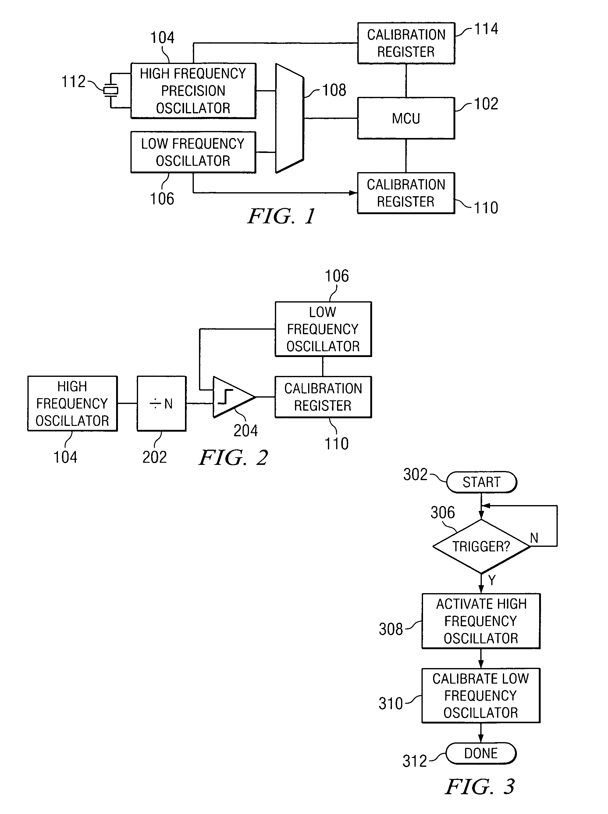
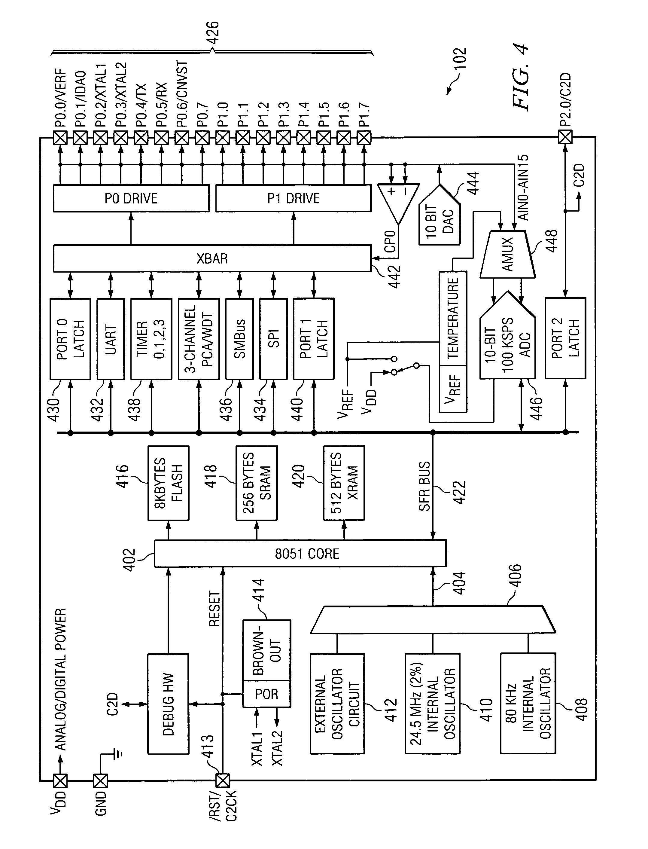
[0014]Referring now to FIG. 1, there is illustrated a diagrammatic view of a processor-based system illustrating the calibratable oscillator section. The processor-based system is comprised primarily of a central processing unit 102 which, in this example, is a micro-controller unit (MCU). This is a conventional device which is comprised of a plurality of functional blocks, such as a processor, a digital I / O and analog-to-digital conversion circuitry. Circuits of this type are typically referred to as system on a chip devices of the type manufactured by Silicon Laboratories, Inc., part No. C8051FXXX. These devices typically include one or more selectable oscillators. In this example, there is illustrated a high frequency precision oscillator 104 and a low frequency oscillator 106. Each of the oscillators provides an output to a multiplexer circuit 108 which drives the operation of the MCU 102. The low frequency oscillator 106 is not crystal controlled and, therefore, is adjustable. ...


PUM


Abstract

Method and apparatus for calibration of a low frequency oscillator in a processor based system. A method for calibrating an on-chip non-precision oscillator. An on-chip precision oscillator is provided having a known frequency of operation that is within an acceptable operating tolerance. The on-chip precision oscillator is used as a time base and then the period of the on-chip oscillator is measured as a function of the time base. The difference between the measured frequency of the on-chip non-precision oscillator and a desired operating frequency of the on-chip non-precision oscillator is then determined. After the difference is determined, the frequency of the on-chip non-precision oscillator is adjusted to minimize the determined difference.

Description

CROSS-REFERENCE TO RELATED APPLICATIONS[0001]This Application is claims benefit of Provisional application Ser. No. 60 / 577,314, filed on Jun. 4, 2004, “METHOD AND APPARATUS FOR CALIBRATION OF A LOW FREQUENCY OSCILLATOR IN A PROCESSOR BASED SYSTEM”TECHNICAL FIELD OF THE INVENTION[0002]The present invention pertains in general to oscillators for use in a processor-based system and, more particularly, to a calibration system for calibrating the oscillator.BACKGROUND OF THE INVENTION[0003]Processor-based systems require a time base in order to operate. This time base can either be an external time base or an internal time base. The time base provides a clock signal that is utilized by the processor-based system to execute various instructions, run internal timers and provide sample clocks to data conversion systems such as analog-to-digital converters and digital-to-analog converters. In some applications, the processor is able to operate at two clock frequencies, a high clock frequency...

Claims


Application Information

Patent Timeline
Patent Type & Authority Patents(United States)
IPC IPC(8): G01R23/10H03B1/00H03L1/02H03L7/08
CPCH03L7/08H03L1/02
Inventor WILSON, BRENTHIGHLEY, PAULFERNALD, KENNETH W.
Owner SILICON LAB INC
Learn More