Flush-mounted low-profile resonant hole antenna

a resonant hole, low-profile technology, applied in the direction of movable body antenna adaptation, slot antenna, radiating element housing, etc., can solve the problem that the shape change of the resonant hole will affect the antenna performan

Active Publication Date: 2012-02-16
ADVANCED AUTOMOTIVE ANTENNAS
View PDF2 Cites 150 Cited by
  • Summary
  • Abstract
  • Description
  • Claims
  • Application Information

AI Technical Summary

Benefits of technology

[0008]The resonant hole may have circular shape with a radius smaller than 1.5 wavelenghts. The wall of the resonant hole is much smaller than one wavelength thus creating a low-profile structure.

Problems solved by technology

The resonant hole wall's shape need not to be circular, however, any change on the shape of the resonant hole will affect the antenna performance.

Method used


Image

  • Flush-mounted low-profile resonant hole antenna
  • Flush-mounted low-profile resonant hole antenna
  • Flush-mounted low-profile resonant hole antenna

Examples


Embodiment Construction

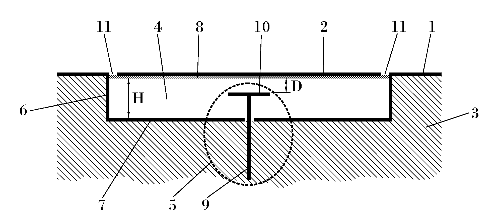
[0027]The flush-mounted low-profile resonant hole antenna system of the invention is intended to be, completely or partially, an integral component of the fuselage (3) of an aircraft, UAV or missile.

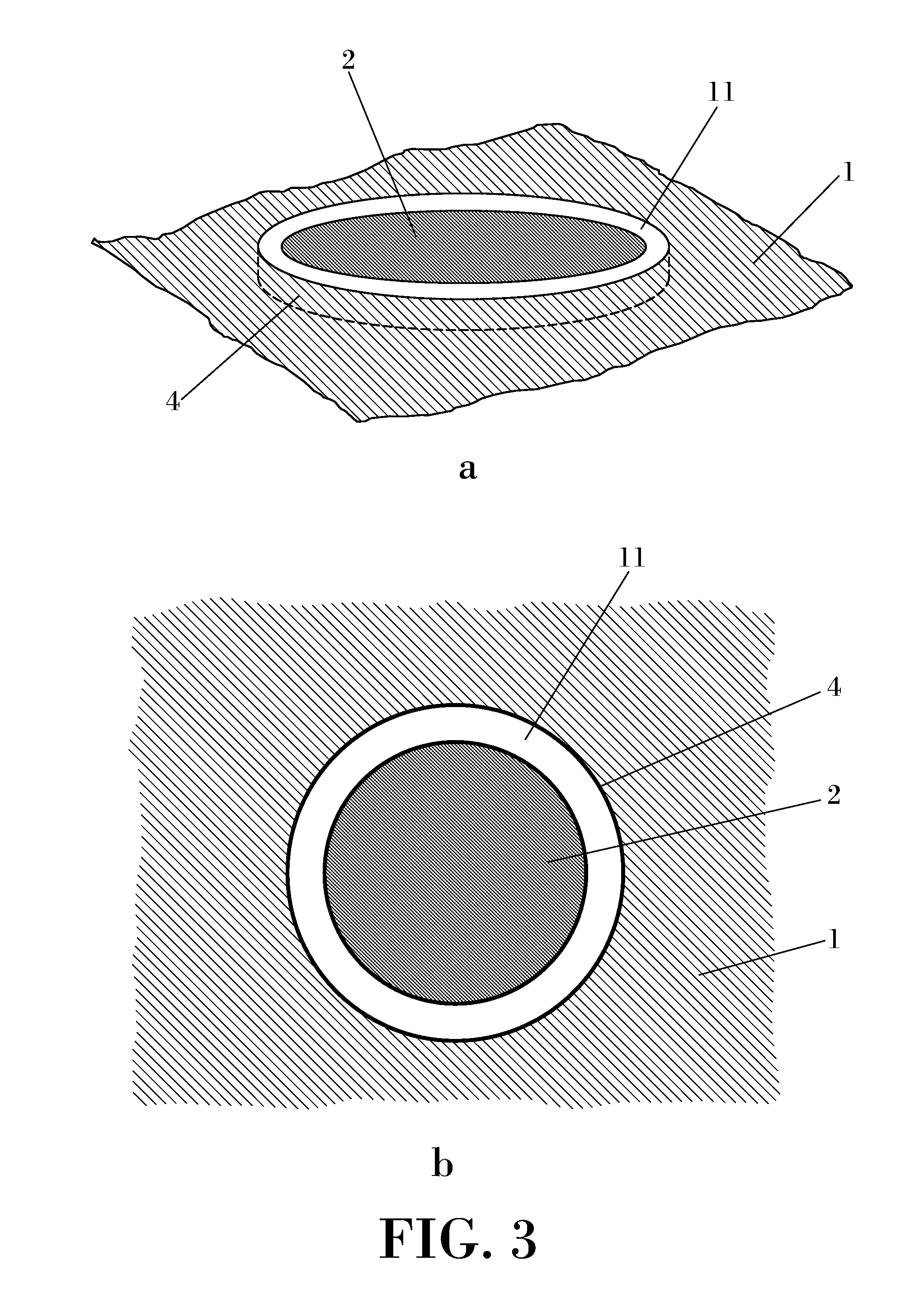
[0028]The antenna system of the invention comprises a surface (1) made of a conductive material and a resonant recess (4) formed in said conductive surface (1). Said recess (4) is an open cavity extending inwardly in said surface, and it is defined by a side wall (6) in the entire perimeter of the cavity, and a bottom wall (7).

[0029]The antenna system further comprises a radiating element (2), so that a major part of the radiating element is housed within said recess. This means that, preferably a major part of the radiating element is housed within the volume defined by said recess.

[0030]A feeding element (5) is provided also within said recess, separated from the radiating element but electromagnetically coupled the radiating element to feed it with an electromagnetic signal.

[0031]The ...


PUM


Abstract

The invention relates to a flush-mounted aircraft, UAV or missile antenna system, which is an integral part of the fuselage (3) of an aircraft, UAV or missile. The antenna system comprises a surface (3) made of a conductive material and a resonant recess (4) formed in said conducting surface, wherein said recess is conformed to provide a resonant behaviour in a selected operating frequency, the antenna system further comprising a radiating element (2) located within said recess and a feeding element (5) within said recess coupled to said radiating element.

Description

OBJECT OF THE INVENTION[0001]An object of this invention is to provide a flush-mounted aircraft, UAV or missile antenna system, that is an integral part of the fuselage of an aircraft, UAV or missile.BACKGROUND OF THE INVENTION[0002]Monopole antennas are currently used in high speed and ultra high speed aircrafts, unmanned aerial vehicles (hereinafter UAVs), missiles, etc. These antennas are normally blade antennas like the one described in FIG. 1. Blade antennas are designed in such a way that the external blade element is attached to the skin of the aircraft, UAV or missile, and extending outwardly therefrom.[0003]The blade antenna shape may affect the aerodynamic performance of high speed and ultra high speed aircrafts, UAVs, missiles, etc. The presence of a blade antenna on the fuselage of the aircraft, UAV or missile may cause problems such as fluid dynamic disturbances, aircraft, missile or UAV vibrations that can affect the antenna performance, or even destroy the antenna its...

Claims


Application Information

Patent Timeline
Patent Type & Authority Applications(United States)
IPC IPC(8): H01Q1/28H01Q1/42
CPCH01Q1/286H01Q9/0442H01Q13/18H01Q9/0457H01Q9/0464
Inventor MONSALVE CARCELEN, BEATRIZQUINTERO ILLERA, RAMIROSANZ ARRONTE, ALFONSOMARTINEZ ORTIGOSA, ENRIQUE
Owner ADVANCED AUTOMOTIVE ANTENNAS
Why Eureka
Try Eureka