
Method of generating accurate estimates of azimuth and elevation angles of a target for a phased-phased array rotating radar

a phased-phased array and azimuth angle technology, applied in direction finders using radio waves, instruments, measurement devices, etc., can solve the problems of not correcting the effects of rotation on a radar employing coherent integration, not using the monopulse process for rotating radars using coherent integration, and not using the coherent integration effect to correct the effects of rotation on a radar employing ci, etc., to achieve accurate calculation of the sine-space offset of the radar targ

Active Publication Date: 2007-07-31
RAYTHEON CO
View PDF8 Cites 34 Cited by
  • Summary
  • Abstract
  • Description
  • Claims
  • Application Information

AI Technical Summary

Benefits of technology

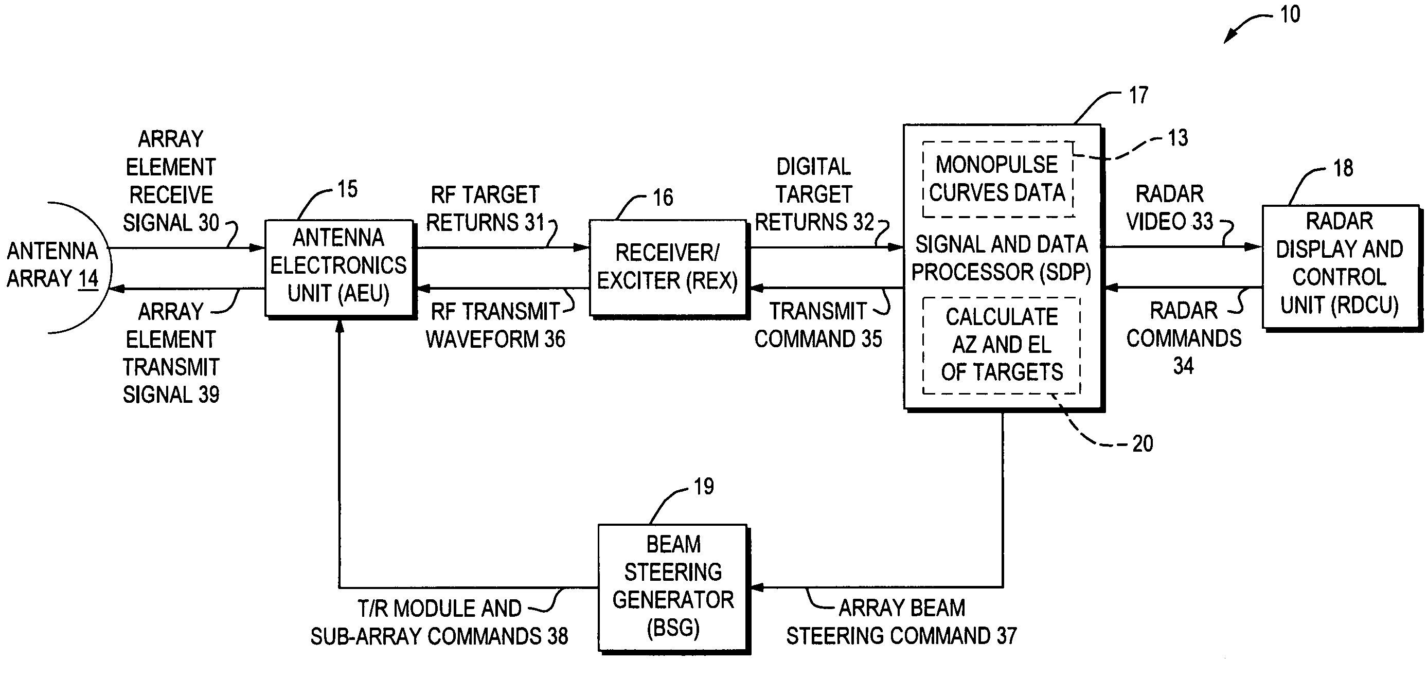
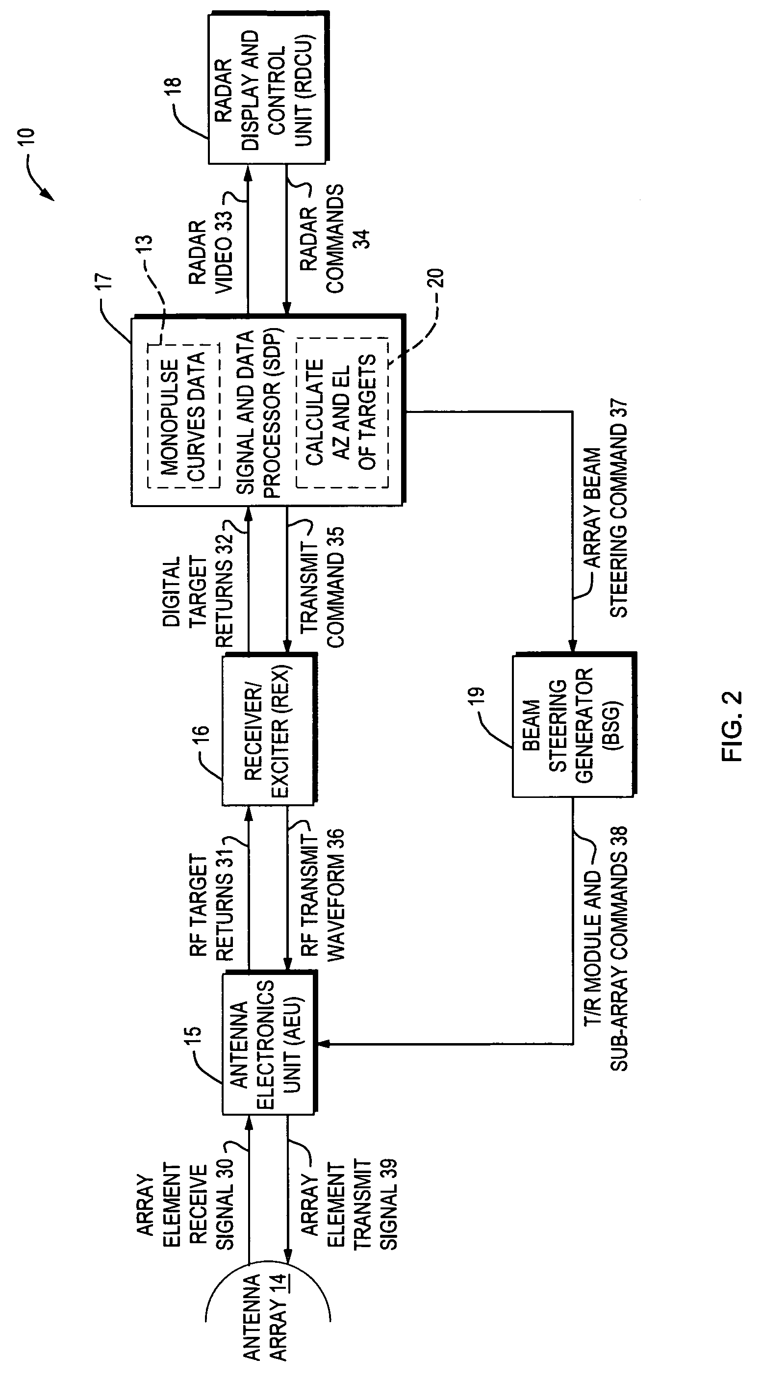
[0011]It is another object of this invention to provide a method for generating scan modulated coherently integrated (SMCI) monopulse curves, and to use these curves to accurately calculate the radar target's sine-space offset from the beam steer. The target's sine-space position is then transformed to azimuth and elevation angles in a fixed non-rotating coordinate system.

Problems solved by technology

The monopulse process has not been employed for rotating radars using coherent integration because the monopulse ratios do not map to the correct target angles when curves developed for a stationary array are used.
However, it does not correct for the effects of rotation on a radar employing coherent integration (CI).
This patent disclosure is an entirely new method of monopulse processing that was designed for a non-rotating radar, and does not correct for the effects of rotation on a radar employing CI.
However, it does not correct for the effects of rotation on a radar employing CI.

Method used


Image

  • Method of generating accurate estimates of azimuth and elevation angles of a target for a phased-phased array rotating radar
  • Method of generating accurate estimates of azimuth and elevation angles of a target for a phased-phased array rotating radar
  • Method of generating accurate estimates of azimuth and elevation angles of a target for a phased-phased array rotating radar

Examples


Embodiment Construction

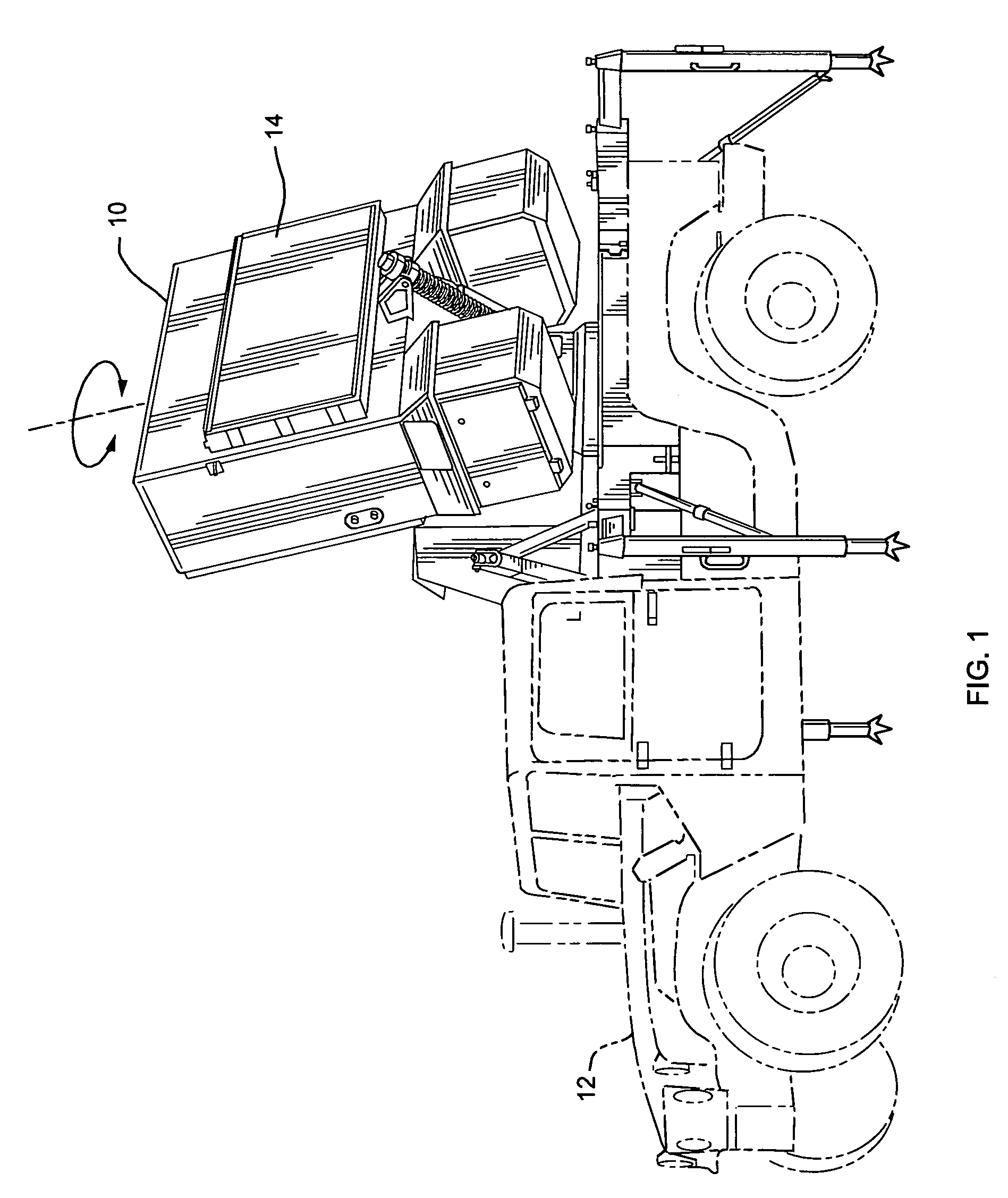
[0033]Referring to FIG. 1, a rotating phased-phased array radar system 10 mounted on the back of a truck-type vehicle 12 is shown, and the radar system 10 employs a method of generating accurate estimates of a target's azimuth and elevation angles according to the present invention.

[0034]An antenna 14 of the phased-phased array rotating radar system 10 moves in azimuth relative to a target as pulses are transmitted and received. As a result, the target returns are scan-modulated by the radar's two-way antenna patterns as the antenna 14 rotates through a dwell, the dwell being the interval of time during which pulses are transmitted and received. Not all of the pulses transmitted are coherently integrated. A small number of the initial pulses are used to fill and settle the signal processing filters. These pulses are called fill pulses. Pulses received after the fill pulses are coherently integrated. The portion of the dwell during which the pulses to be coherently integrated are tra...


PUM


Abstract

A method and apparatus for generating accurate estimates of a radar target's azimuth and elevation angles for a phased-phased array rotating radar. Scan modulated coherently integrated (SMCI) monopulse curves are generated from a measured one-way transmit antenna pattern and three receive antenna patterns. The SMCI monopulse curves are calculated in advance for the expected beam steers. To utilize the SMCI monopulse curves, two-way Sum, Delta-Azimuth and Delta-Elevation target returns are coherently integrated, the target's monopulse ratios calculated, and the SMCI monopulse curves or polynomials used to calculate the target's U-offset and V-offset sine-space angles, which are added to the radar's beam steer to get an improved estimate of the target's sine-space angular position denoted as Utgt and Vtgt. A coordinate system transformation transforms Utgt and Vtgt to azimuth and elevation angles in a non-rotating coordinate system.

Description

BACKGROUND OF THE INVENTION[0001]1. Field of the Invention[0002]This invention relates generally to a rotating phased-phased array radar, and in particular to a method of generating accurate estimates of azimuth and elevation angles of a radar target using pre-calculated monopulse curves for a rotating monopulse radar using coherent integration of pulse returns.[0003]2. Description of Related Art[0004]An antenna of a mechanically rotating radar moves in azimuth relative to a target as pulses are transmitted and received. As a result, the pulse returns are scan-modulated by the radar's two-way antenna patterns. In other words, the pulses experience dissimilar antenna pattern gains as the array rotates. Coherent integration of the pulse returns is done to increase the signal-to-noise ratios (SNRs) of the received signals prior to detection and target angle estimation. Non-rotating radars frequently employ the monopulse method for angle measurement. This process involves forming monopu...

Claims


Application Information

Patent Timeline
Patent Type & Authority Patents(United States)
IPC IPC(8): G01S13/44G01S3/72
CPCG01S13/4418G01S7/2925G01S7/2926G01S7/4026G01S2007/403G01S13/4463G01S2007/4034G01S7/4034G01S7/403G01S13/44G01S13/72
Inventor MANOOGIAN, DAVID V.PITSTICK, GERALD M.CANGEME, JOHN
Owner RAYTHEON CO
Learn More