Multi-purpose electromagnetic radiation interface system and method

Active Publication Date: 2007-07-31
THE UNITED STATES OF AMERICA AS REPRESENTED BY THE SECRETARY OF THE NAVY
View PDF9 Cites 25 Cited by
  • Summary
  • Abstract
  • Description
  • Claims
  • Application Information

AI Technical Summary

Benefits of technology

[0031]Another object is to provide a system that may have improved stealth characteristics.
[0032]A

Problems solved by technology

Thus, according to traditional antenna theory it is impossible to provide a wide bandwidth antenna with a small capture area.
Moreover, prior art broadband receiving systems are performance limited by the inability to realize sufficient spurious-free dynamic range (SFDR) in the analog portions of the receiving systems.
Prior art broadband receiving systems may often be limited to about 60 db SFDR.
Prior art antennas are also limited as to the type of functions that are available.
Generally, prior art antennas are dedicated to perform a certain function and are not suitable for other specific functions.
However, a prior antenna design will not be useable for

Method used


Image

  • Multi-purpose electromagnetic radiation interface system and method
  • Multi-purpose electromagnetic radiation interface system and method
  • Multi-purpose electromagnetic radiation interface system and method

Examples


Embodiment Construction

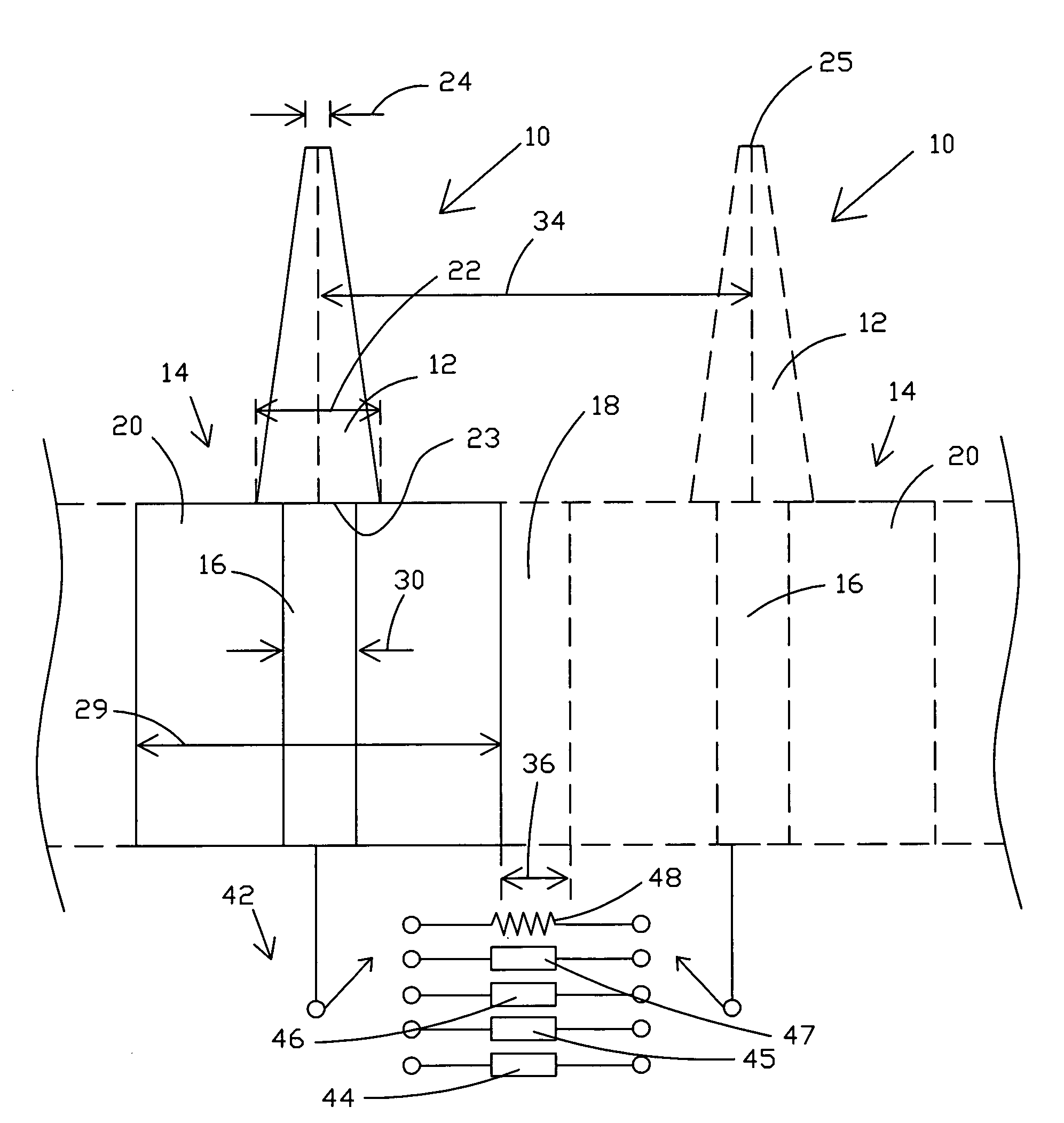
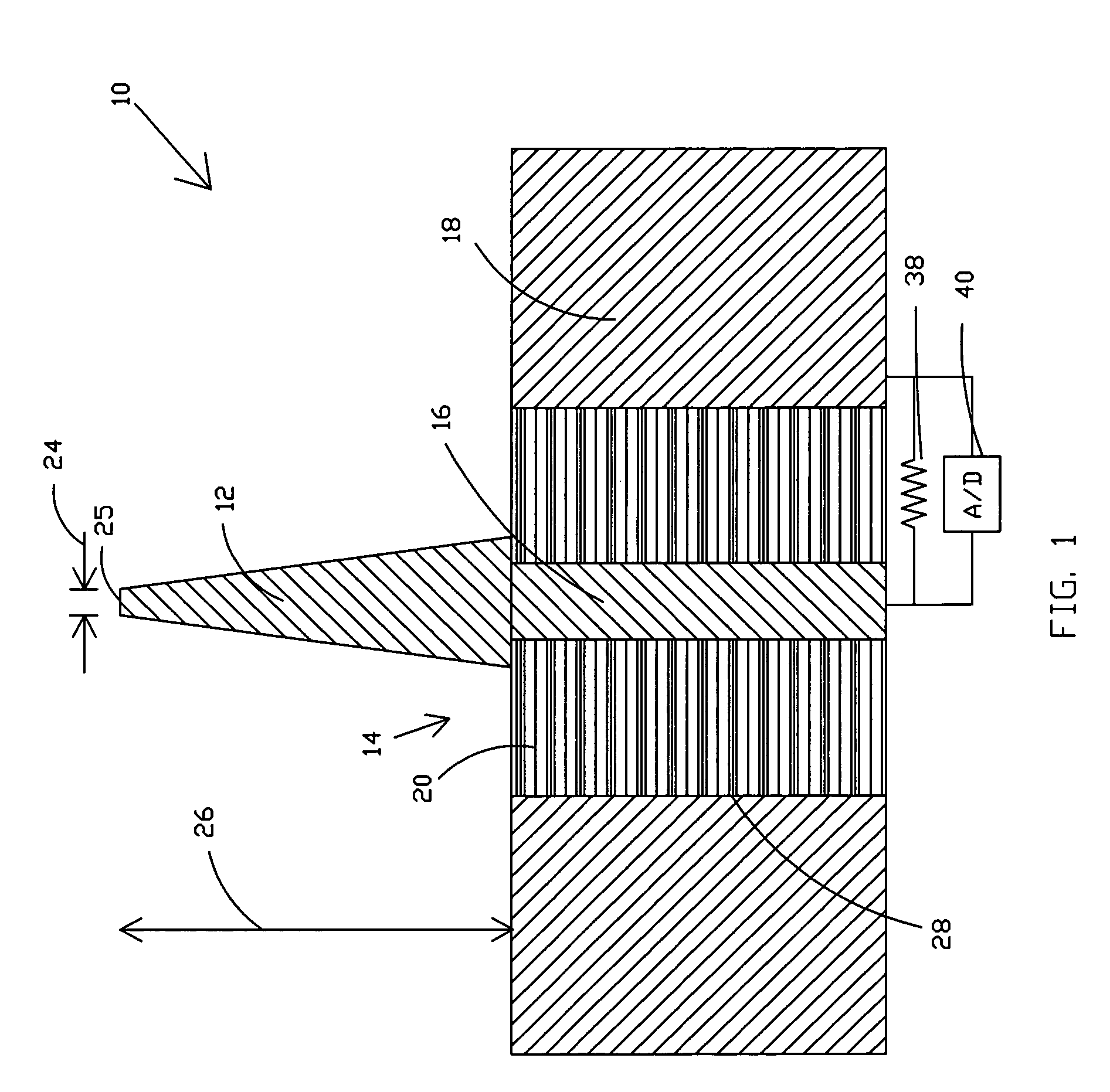
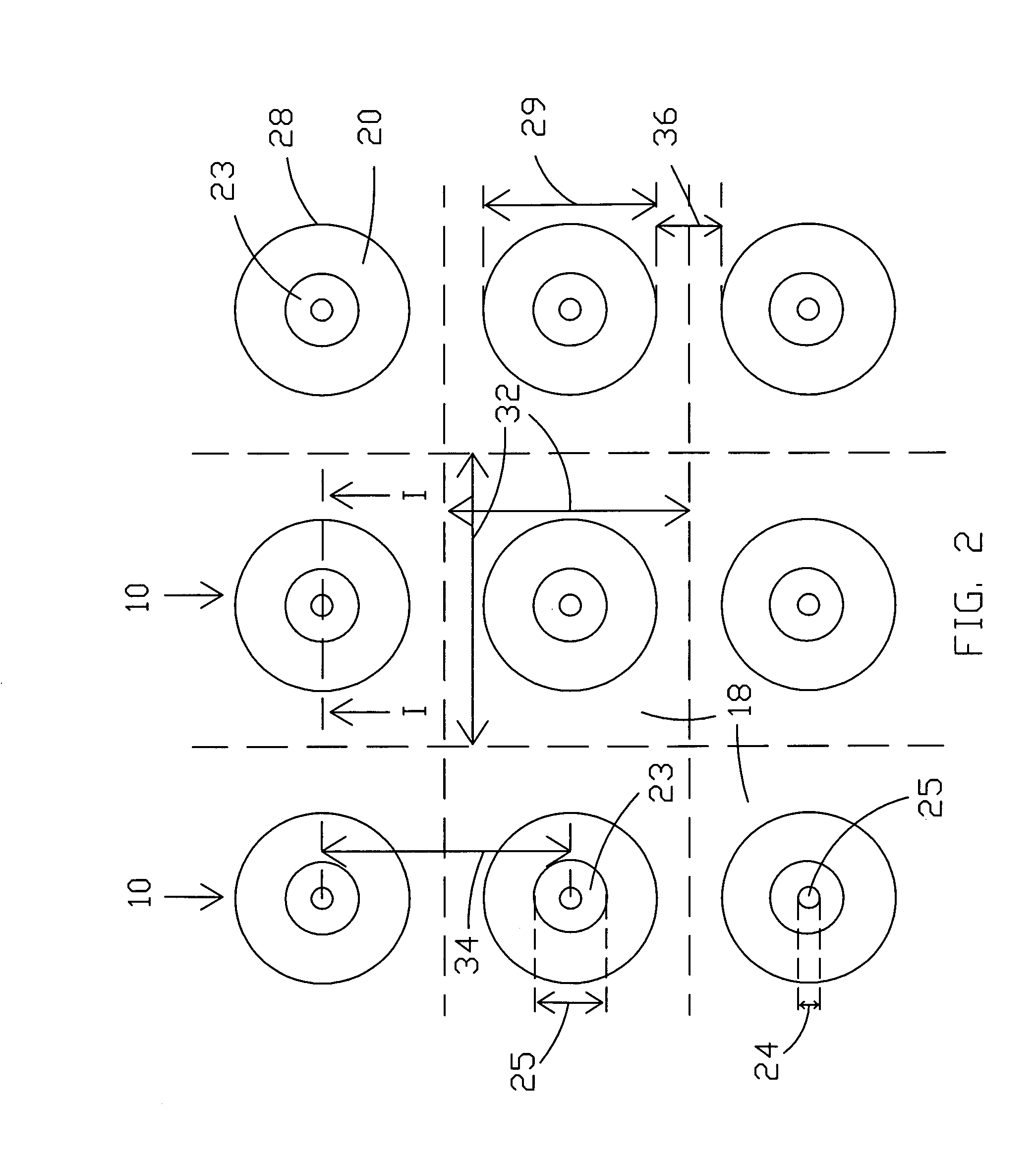
[0048]The present invention provides an electromagnetic radiation interface whose basic construction may be utilized to perform widely divergent functions, some of which are discussed hereinafter. Technically, the present invention is not an antenna in the traditional sense. An antenna in the traditional sense implies a device with a single port that can be coupled to a transmitter or a receiver. The present invention provides an air or space interface between a wide bandwidth of electromagnetic radiation and one or more processors. In one embodiment, different types of processors may be selectable so that the function of the interface is then also selectable. The present invention may be utilized as an antenna if all energy from each of the sensor elements, discussed hereinafter, is coherently recombined in an electronic system coupled to the elements of the surface. However, in another embodiment, the present invention may be utilized as an electrically “black” air or space interf...


PUM


Abstract

An electromagnetic radiation interface is provided that is suitable for use with radio wave frequencies. A surface is provided with a plurality of electrically conductive bristles. A corresponding plurality of termination sections are provided so that each bristle is terminated with a termination section. The termination section may comprise one or more different termination packages for operating on received electromagnetic radiation and/or producing desired reflections and transmissions. In one embodiment, switches and termination packages may be implemented within integrated circuits wherein the switches may be utilized to switch between different termination packages. The termination packages may include selected fixed reactances and/or modulators designed to produce desired reflections, e.g., Doppler effects to make it appear the surface of the interface is moving a speed different than the actual speed.

Description

STATEMENT OF GOVERNMENT INTEREST[0001]The invention described herein may be manufactured and used by or for the Government of the United States of America for governmental purposes without the payment of any royalties thereon or therefore.CROSS-REFERENCE TO RELATED APPLICATIONS[0002]This patent application is related to co-pending U.S. patent application entitled ELECTROMAGNETIC RADIATION INTERFACE SYSTEM AND METHOD Application Ser. No. 10 / 956,526 having same filing date, which is hereby incorporated by reference in its entirety.BACKGROUND OF THE INVENTION[0003](1) Field of the Invention[0004]The present invention relates generally to systems for controlling electromagnetic radiation, and more particularly to an electromagnetic wave interface that may be utilized to capture electromagnetic radiation such as radio waves and transform the radiation by some desired means such as by absorbing the radiation completely for stealth purposes, reflecting the radiation with desired characteri...

Claims


Application Information

Patent Timeline
IPC IPC(8): H01Q21/00
CPCH01Q17/00H01Q21/061H01Q23/00
Inventor STEINBRECHER, DONALD H.
Owner THE UNITED STATES OF AMERICA AS REPRESENTED BY THE SECRETARY OF THE NAVY
Why Eureka
Try Eureka