Methods and apparatus for actuating a downhole tool

Inactive Publication Date: 2007-08-07
WEATHERFORD TECH HLDG LLC
View PDF49 Cites 194 Cited by
  • Summary
  • Abstract
  • Description
  • Claims
  • Application Information

AI Technical Summary

Problems solved by technology

There are drawbacks to using tripping devices such as a ball.
Since the tripping device is designed to land in the downhole tool, the inner diameter of the downhole tool is, in turn, limited by the size of the tripping device.
Limitations on the bore size of the downhole tool are a drawback of the efficiency of the downhole tool.
Another drawback of tripping devices is reliability.
In some instances, the tripping device does not securely seat in the downhole tool.
It has also been observed that the tripping device does not reach the downhole tool due to o

Method used


Image

  • Methods and apparatus for actuating a downhole tool
  • Methods and apparatus for actuating a downhole tool
  • Methods and apparatus for actuating a downhole tool

Examples


Embodiment Construction

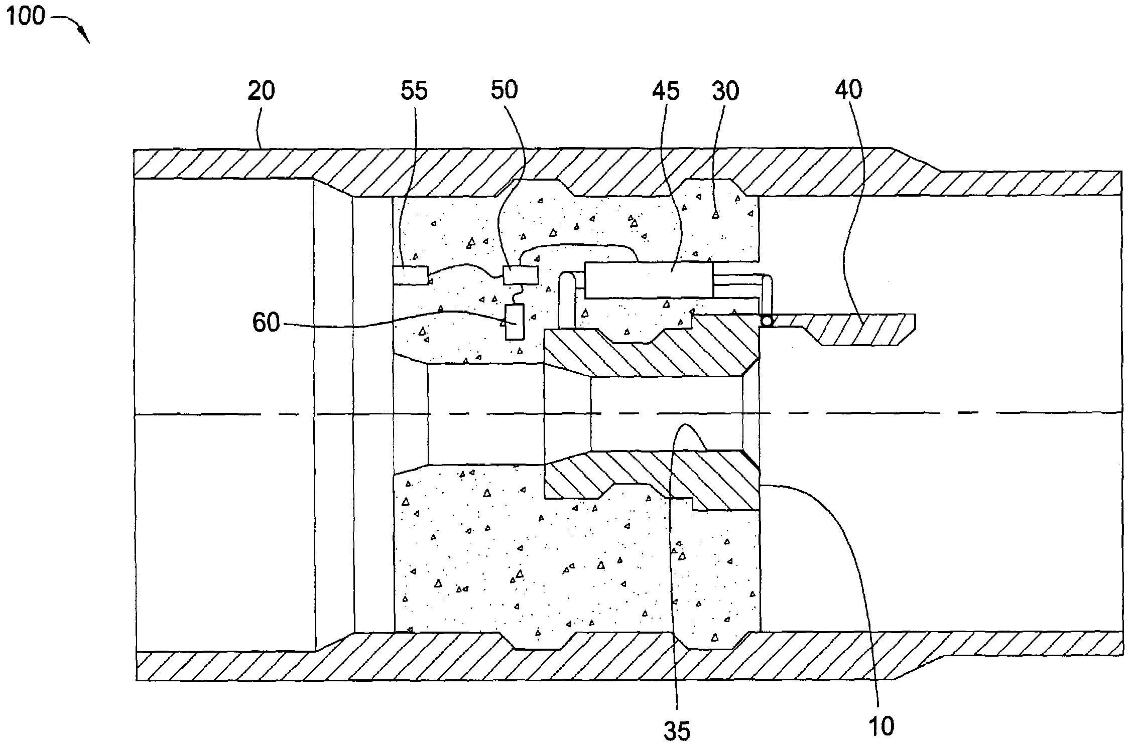
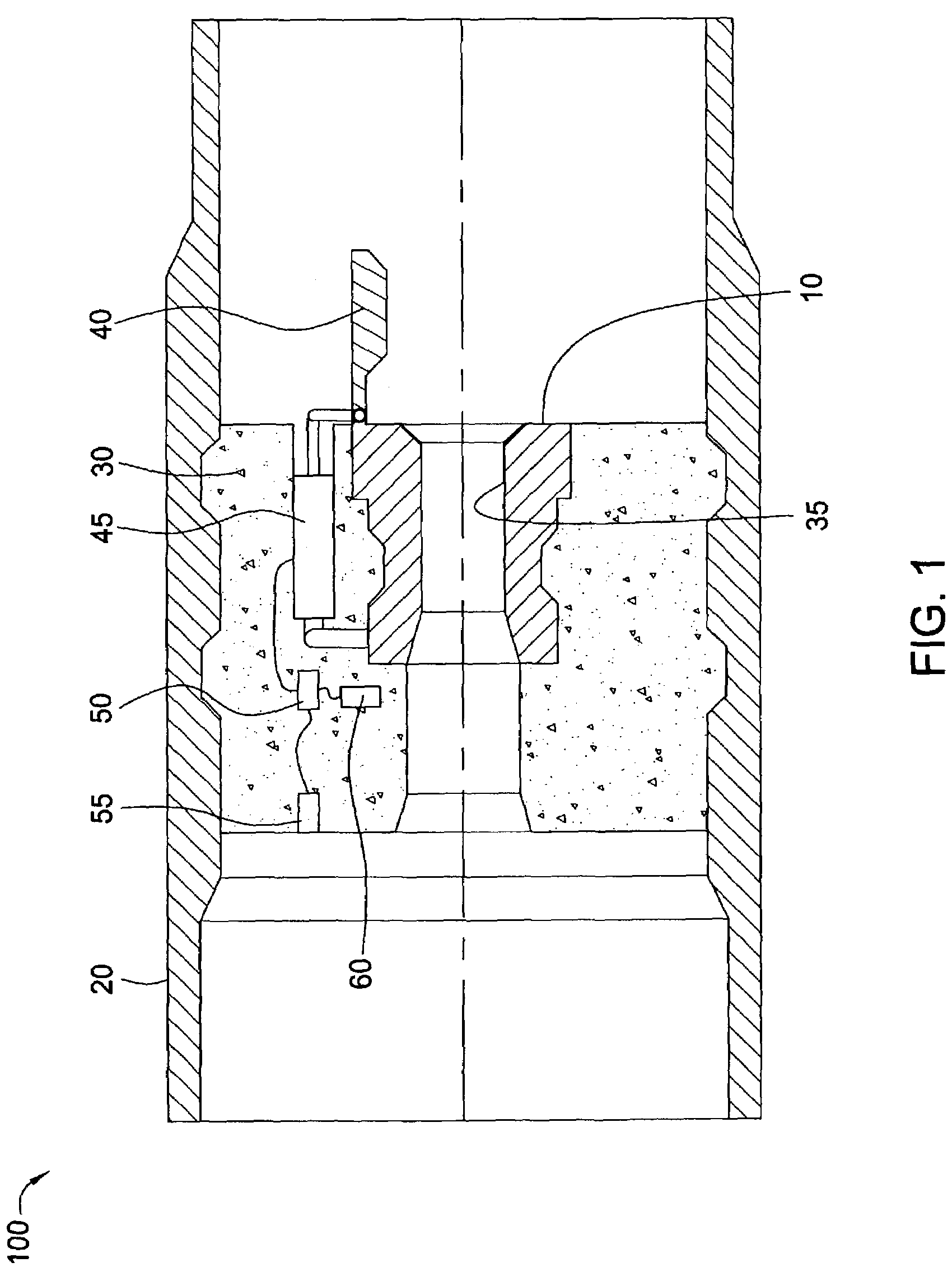
[0030]Aspects of the present invention generally relate to operating a downhole tool. Particularly, the present invention relates to apparatus and methods for remotely actuating a downhole tool. In one aspect, the present invention provides a sensor, controller, and an actuator for actuating the downhole tool. The sensor is adapted to monitor, detect, or measure conditions in the wellbore. The sensor may transmit the detected conditions to the controller, which is adapted to operate the downhole tool according to a predetermined downhole tool control circuit.

Remotely Actuated Float Valve Assembly

[0031]FIG. 1 is a schematic illustration of a remotely actuatable float valve assembly 100 according to aspects of the present invention. As shown, a float valve 10 is disposed in a float collar 20. The float collar 20 may be assembled as part of the float shoe. Additionally, the float valve 20 may attach directly to the float shoe. In one embodiment, cement 30 is used to mount the float val...


PUM


Abstract

The present invention relates to apparatus and methods for remotely actuating a downhole tool. In one aspect, the present invention provides an apparatus for activating a downhole tool in a wellbore, the downhole tool having an actuated and unactuated positions. The apparatus includes an actuator for operating the downhole tool between the actuated and unactuated positions; a controller for activating the actuator; and a sensor for detecting a condition in the wellbore, wherein the detected condition is transmitted to the controller, thereby causing the actuator to operate the downhole tool. In one embodiment, conditions in the wellbore are generated at the surface, which is later detected downhole. These conditions include changes in pressure, temperature, vibration, or flow rate. In another embodiment, a fiber optic signal may be transmitted downhole to the sensor. In another embodiment still, a radio frequency tag is dropped into the wellbore for detection by the sensor.

Description

BACKGROUND OF THE INVENTION[0001]1. Field of the Invention[0002]Aspects of the present invention generally relate to operating a downhole tool. Particularly, the present invention relates to apparatus and methods for remotely actuating a downhole tool. More particularly, the present invention relates to apparatus and methods for actuating a downhole tool based on a monitored wellbore condition.[0003]2. Description of the Related Art[0004]In the drilling of oil and gas wells, a wellbore is formed using a drill bit that is urged downwardly at a lower end of a drill string. After drilling a predetermined depth, the drill string and bit are removed and the wellbore is lined with a string of casing. An annular area is thus formed between the string of casing and the formation. A cementing operation is then conducted in order to fill the annular area with cement. The combination of cement and casing strengthens the wellbore and facilitates the isolation of certain areas of the formation b...

Claims


Application Information

Patent Timeline
IPC IPC(8): E21B34/06E21B33/14E21B47/09E21B23/00E21B44/00E21B47/00
CPCE21B17/1028E21B23/00E21B41/00E21B44/005E21B47/00E21B34/066E21B17/1014E21B21/10E21B2200/05E21B47/12E21B17/10E21B47/18E21B47/135E21B47/13E21B34/06
Inventor LOGIUDICE, MICHAELCOLVARD, R. LEE
Owner WEATHERFORD TECH HLDG LLC
Why Eureka
Try Eureka