
Motorcycle headlight assembly

a headlight assembly and motorcycle technology, applied in the direction of cycle equipment, lighting and heating apparatus, lighting support devices, etc., can solve the problem that the headlights of the conventional type do not enable fine adjustment in the direction, and achieve the effect of facilitating the assembly process, more stability and robustness

Inactive Publication Date: 2007-08-07
HONDA MOTOR CO LTD
View PDF19 Cites 3 Cited by
  • Summary
  • Abstract
  • Description
  • Claims
  • Application Information

AI Technical Summary

Benefits of technology

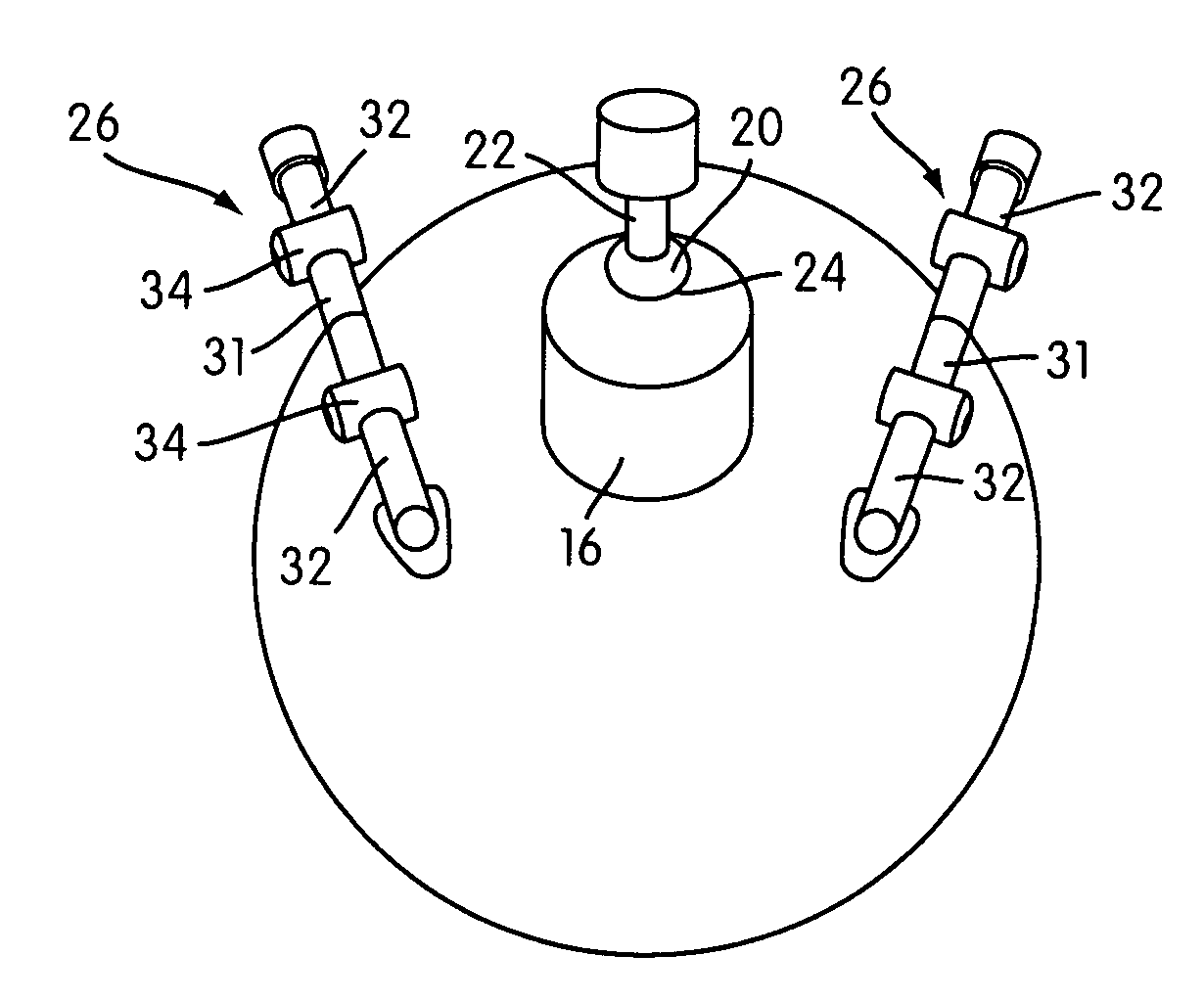
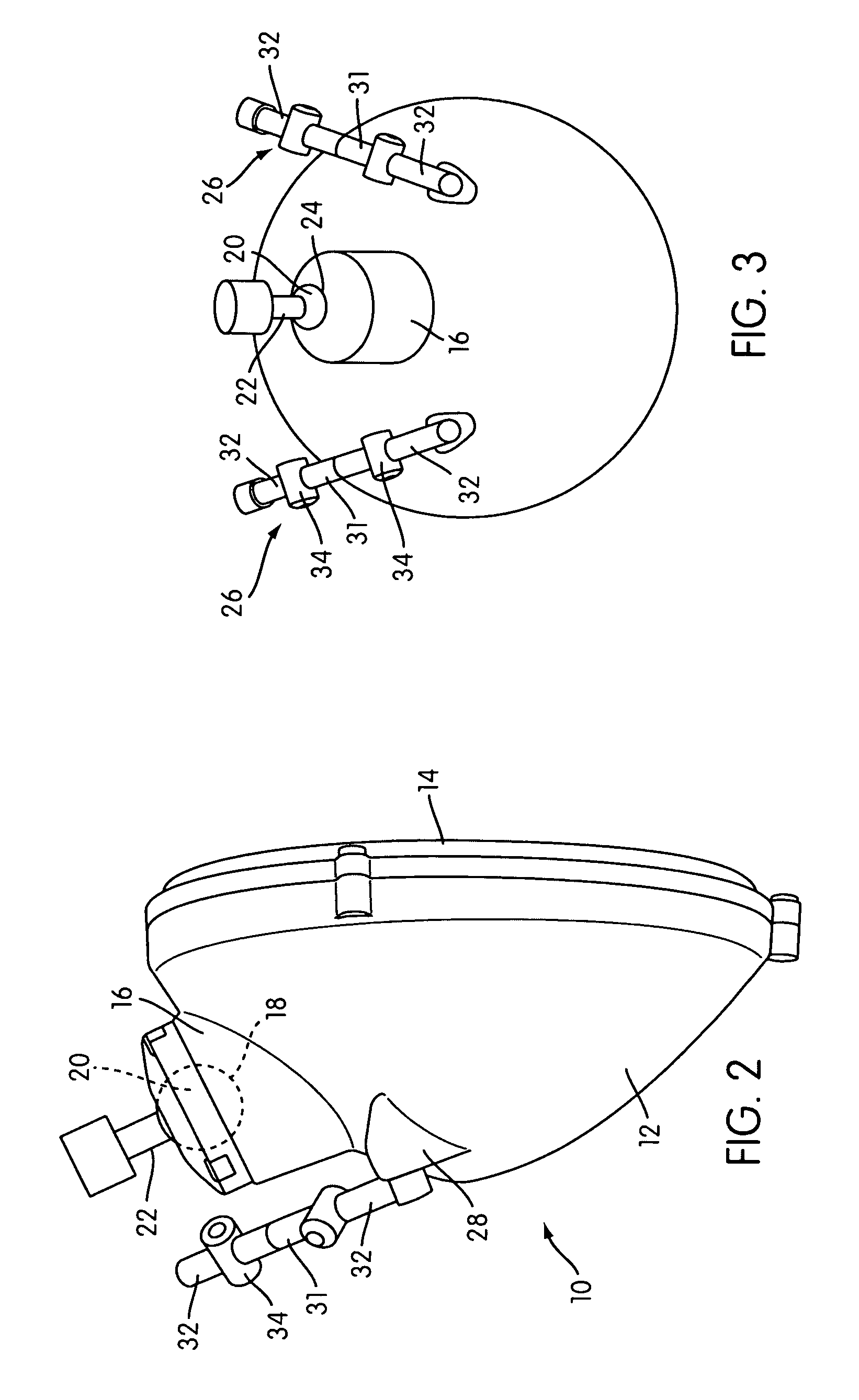
[0006]An adjustable motorcycle headlight with multiple degrees of freedom enables the rider to aim the light where it is needed most for the particular condition, as well as facilitating the assembly process by enabling adjustment after the headlight is mounted. The mounting structure comprises more than a single point attachment or upper and lower attachments to provide more stability and robustness than conventional assemblies. The motorcycle headlight is attached to the frame via a ball and socket structure cooperatively coupled to at least one positioning adjuster. The headlight housing has an integrated boss on its rear side in which is provided the socket for a ball and socket structure. The counterpart ball portion of the joint is affixed to the frame. In addition to the ball and socket structure, at least one positioning arm is provided in tandem therewith for accommodating and stabilizing the movement of the ball and socket joint and locking same in position. Preferably two positioning arms are employed, on either side of the ball and socket structure and attached to the boss so as to form a three point attachment of the headlight to the frame.
[0007]Each positioning arm has one end rotatably attached to a retaining boss on the headlight housing, and the opposite end rotatably attached to the frame in a similar fashion. Between the two ends, each positioning arm comprises a series of straight segments joined by adjusters and movable joints. Moving from the headlight housing toward the frame, a single straight segment is mounted into the retaining boss of the headlight housing, and this single straight segment is joined to a double straight segment by an adjuster. The double straight segment comprises two straight segments joined together by a specially configured male-female coupling that allows rotating and pivoting movement between these segments. The double straight segment is joined to another single straight segment by another adjuster. This upper single straight segment is attached to the frame. The adjusters are threaded members which can be loosened to enable adjustment of the segments and then tightened to rigidly affix the elements of the positioning arm in place. The straight segments rotate relative to one another to provide for adjustment. The length of the positioning arm can be adjusted by adjusting the angle between the straight segments of the positioning arm. That is, the smaller the angle between straight segments, the shorter the overall length of the positioning arm.
[0008]Two positioning arms of identical construction provided each on either side of the ball and socket structure enable adjustment of the headlight with multiple degrees of freedom. This also provides a three point attachment that is more stable than conventional mounting assemblies.
[0009]The adjustable mounting assembly provides greater tolerances for initial assembly of the headlight onto the frame since adjustments to fit the headlight assembly into place with respect to neighboring components is eased.

Problems solved by technology

Conventional headlights do not enable fine adjustment in the direction of the light so an auxiliary light source may be required or a rider may have to proceed without proper illumination.

Method used


Image

  • Motorcycle headlight assembly
  • Motorcycle headlight assembly
  • Motorcycle headlight assembly

Examples


Embodiment Construction

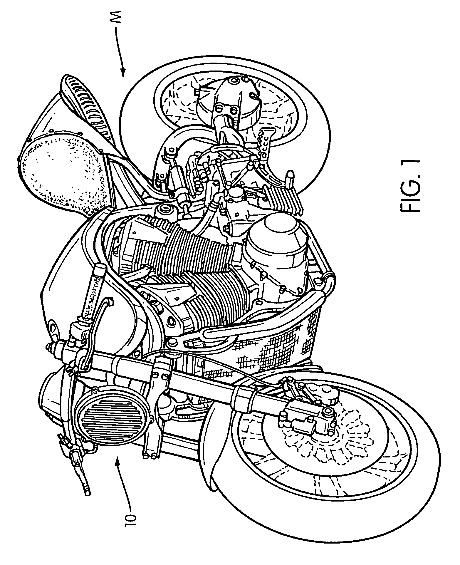
[0019]On a motorcycle M, FIG. 1, motorcycle headlight assembly 10 comprises a headlight housing 12 and a lens 14 on the forward side. Headlight housing 12, FIGS. 2–4, includes an integral boss 16 in which is formed a socket 18 which receives mating ball 20 to form a ball and socket joint structure. Ball 20 is provided at the end of a ball shaft 22, the other end of which is rigidly affixed to the frame in a known manner. Boss 16 is preferably disposed on the top, rear portion of housing 12 such that ball shaft 22 can be attached to the frame in a downwardly extending orientation. Opening 24 in boss 16 defines the periphery of the contact surface of ball shaft 22, and therefore the range of motion of the ball and socket relative to one another. The ball and socket structure are similar to conventional structures for headlight mounting assembles. The ball and socket arrangement enables rotational motion and translational motion in all directions. With respect to the ball and socket jo...


PUM


Abstract

An adjustable motorcycle headlight with multiple degrees of freedom enables the rider to aim the light where it is needed, as well as facilitating the factory assembly process by enabling fine adjustment after the headlight is mounted. The motorcycle headlight is attached to the frame via a ball and socket structure cooperatively coupled to at least one positioning arm provided in tandem with the ball and socket structure for accommodating and stabilizing the movement of the ball and socket joint and locking same in position. The positioning arm includes a series of straight segments rotatably attached to one another via adjusters which can be loosened to enable adjustment, and tightened to affix the positioning arm into place. The combination of the ball and socket joint with a pair of positioning arms also provides a stable, robust three-point attachment mount for the headlight.

Description

BACKGROUND OF THE INVENTION[0001]1. Field of the Invention[0002]A motorcycle headlight assembly having a ball and socket joint and adjustable positioning arms between the headlight and the mounting frame enables fine adjustment of the headlight with multiple degrees of freedom, and a stable, robust mounting assembly after adjustment.[0003]2. Background of the Invention[0004]Conventionally motorcycle headlights are generally rigidly affixed to a mounting frame and cast light in a predetermined, fixed field. Conventional headlight assemblies typically consist of an upper mounting bracket and a lower mounting bracket. The upper mounting bracket may be a ball and socket type of joint. The lower mounting bracket sometimes incorporates a spring and allows for some vertical adjustment of the headlight. The conventional brackets and the headlight need to be assembled with relatively tight tolerances in order to maintain the predetermined aim of the headlight in accordance with traffic and s...

Claims


Application Information

Patent Timeline
Patent Type & Authority Patents(United States)
IPC IPC(8): F21S8/10F21V14/04
CPCB60Q1/068B62J6/02B60Q2200/32B62J6/027
Inventor JAMES, JESSE G.
Owner HONDA MOTOR CO LTD
Learn More