Silicone-filled casing for use with light-emitting unit and method of manufacturing the light-emitting unit

a technology of light-emitting units and silicon-filled casings, which is applied in the direction of semiconductor devices for light sources, light-emitting devices, point-like light sources, etc., can solve the problems of reducing the reliability of the product, so as to achieve excellent heat release performan

Inactive Publication Date: 2007-08-07
TOKI
View PDF5 Cites 22 Cited by
  • Summary
  • Abstract
  • Description
  • Claims
  • Application Information

AI Technical Summary

Benefits of technology

[0006]The present invention has been made in view of the foregoing circumstances and an object thereof is to provide a casing, for use with light-emitting unit, which shows excellent heat release performance and a method of manufacturing such light-emitting unit.
[0009]According to this embodiment, the fluid material flows through sequentially in the order of the injection opening, the passage, the first-member side space, the second-member side space and finally the discharge opening, so that the light-emitting unit is at all times completely filled with the fluid material leaving no space therebetween. Thereby, no air or air bubbles remains inside the light-emitting unit. Hence, the heat arising from light emitting elements and substrate is efficiently conducted and conveyed to the fluid material and the casing for use with light-emitting unit. Accordingly, the thermal release performance can be raised by a simple process and at low cost.
[0011]There may be provided a concave or the like on an outer surface of the second member and there is provided a discharge opening in part of a bottom face of the concave. In such a case, the fluid material is injected and then the injection of the fluid material is stopped when the discharge of the fluid material starts. Then, a small amount of the fluid material that has overflowed from the discharge opening stays in the concave, and the fluid material does not drip out. Moreover, the material that overflows from the discharge opening can stay collected up to as much as volume corresponding to the concave, so that the amount of fluid material to be injected can be calculated in advance and controlled within an appropriate range. Moreover, the bottom face area of the concave is larger than the opening area of the discharge opening. Thus, it is easy to observe and monitor how the air bubbles float out of the hollow area if implemented is a structure such that the discharged fluid material is collected in the concave. Accordingly, no air or air bubbles remains inside the light-emitting unit and the thermal emission performance is raised.
[0012]The discharge opening may be formed in such a manner that an opening area of the discharge opening is larger than that of the injection opening. This structure facilitates smoother and faster movement of the fluid material in the direction from the injection opening toward the discharge opening and, together with the smooth and fast flow, facilitates discharging outside the air bubbles in the light-emitting unit. Thus, no air or air bubbles is allowed to remain inside the light-emitting unit, so that the thermal emission performance can be raised.
[0015]According to this embodiment, the light-emitting unit can be filled with the fluid material while the air bubbles inside the light-emitting unit are being discharged efficiently to the outside thereof. Thus, the light-emitting unit having high thermal exhaust performance can be manufactured in a simpler manner.

Problems solved by technology

However, when such resin liquid is injected into the casing through a hole made therein, air bubbles tend to form in the liquid resin, which may deprive the material of necessary thermal conductivity.
Furthermore, such air bubbles showing on the surface would give a poor appearance to the product and an impression of low product reliability.
To remove the air bubbles, additional processes are required, thus making the manufacturing of the illuminator more complex and consequently raising the unit cost of the product.

Method used


Image

  • Silicone-filled casing for use with light-emitting unit and method of manufacturing the light-emitting unit
  • Silicone-filled casing for use with light-emitting unit and method of manufacturing the light-emitting unit
  • Silicone-filled casing for use with light-emitting unit and method of manufacturing the light-emitting unit

Examples


Embodiment Construction

[0027]The invention will now be described based on the following embodiments which do not intend to limit the scope of the present invention but exemplify the invention. All of the features and the combinations thereof described in the embodiments are not necessarily essential to the invention.

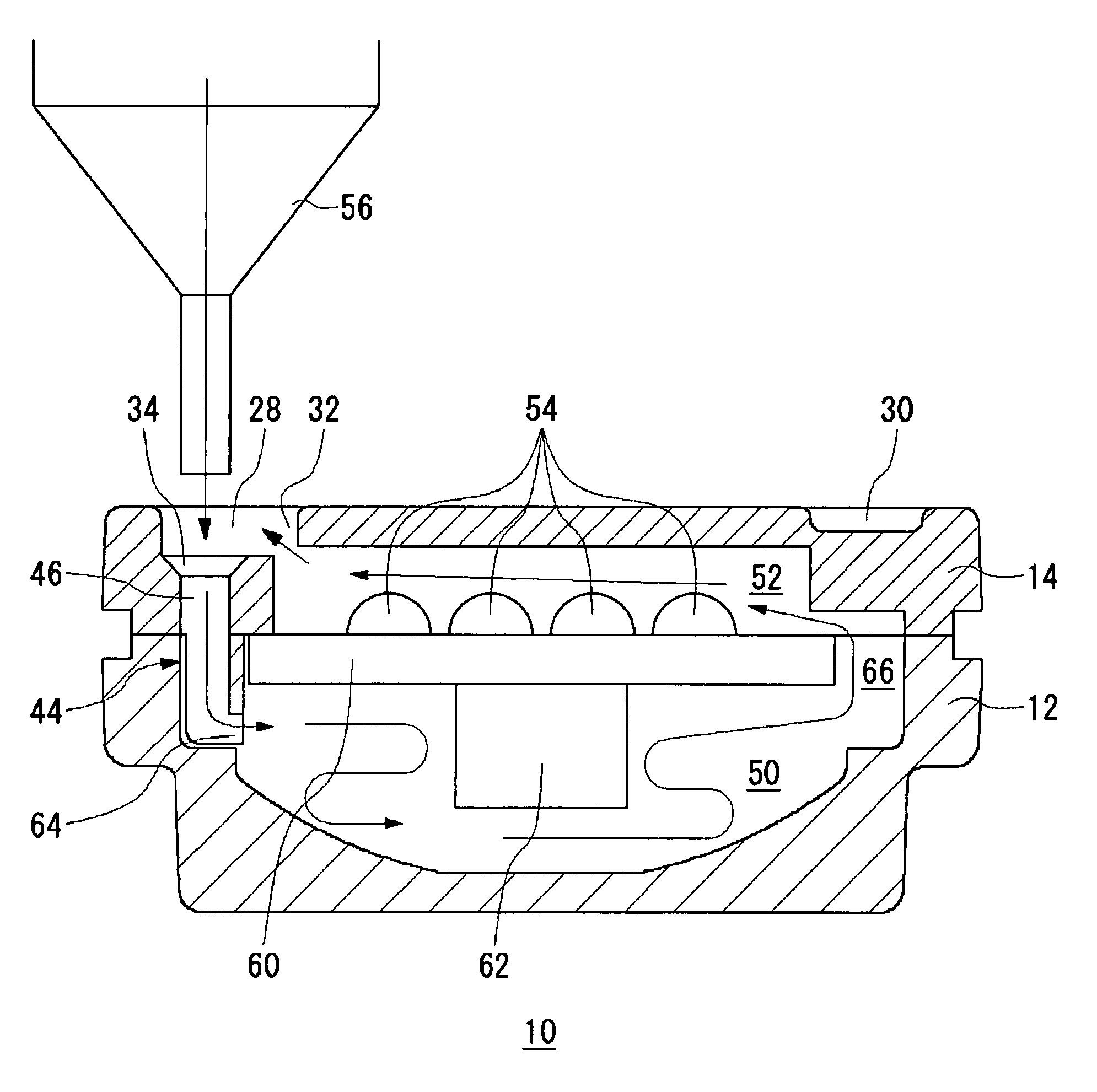
[0028]A light-emitting unit according to the present embodiments has silicone filled in its casing, which is free from air or air bubbles remaining therewithin. This internal condition ensures a high thermal conductivity from the inside of the casing to the outside, thereby releasing the heat arising from light-emitting elements and substrate to the outside efficiently.

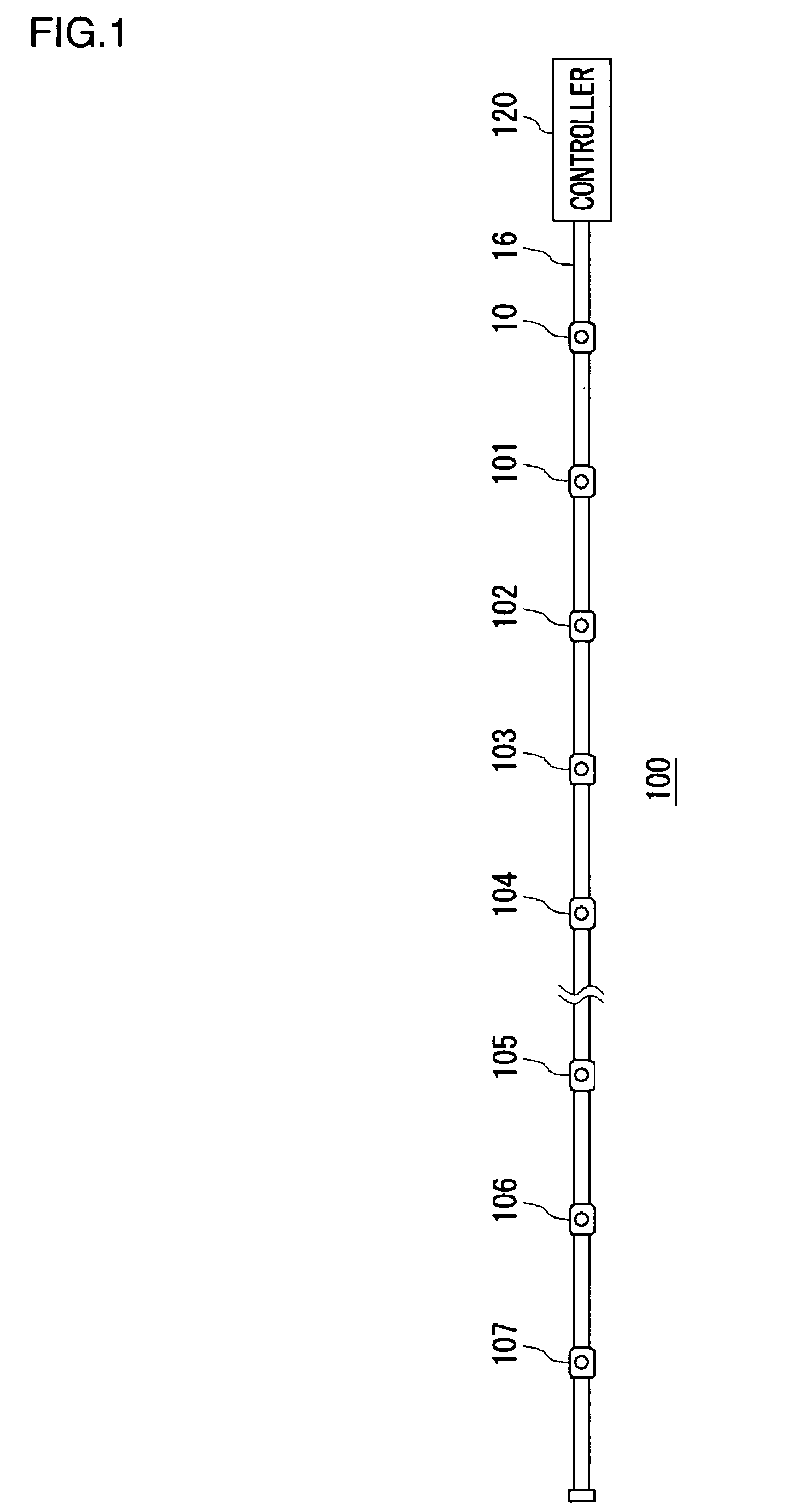
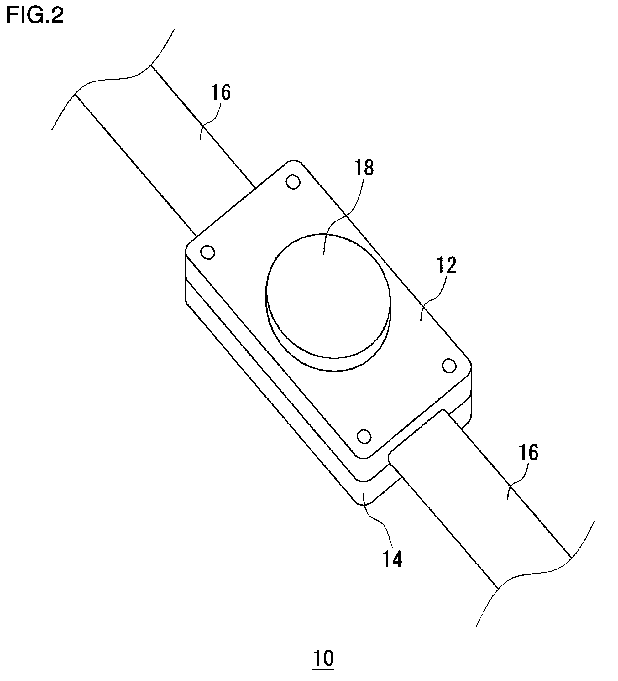
[0029]FIG. 1 shows a structure of an illuminating apparatus wherein a plurality of light-emitting units are connected. The illuminating apparatus shown in FIG. 1 is what is called “tape light”, an outdoor or indoor decorative illumination used in commercial spaces. An illuminating apparatus 100 comprises a controller 120, a cabl...


PUM

PropertyMeasurementUnit
areaaaaaaaaaaa
shapeaaaaaaaaaa
transparentaaaaaaaaaa

Abstract

A light-emitting unit containing a substrate and light emitting diodes (LEDs) is housed inside a casing constituted by a first member and a second member which are joined together. The second member has a projecting piece which is inserted to the first member, and inside the projecting piece a passage is formed. When silicone is injected through an injection opening from an injector, the silicone starting from the projecting piece flows through in the order of the passage, first-member side space, connecting passage and second-member side space and it finally overflows from a discharge opening. By implementing this structure and process, the air or air bubbles inside the light-emitting unit is pushed outside completely.

Description

BACKGROUND OF THE INVENTION[0001]1. Field of the Invention[0002]The present invention relates to casings for use with light-emitting units and a method of manufacturing the light-emitting units, and it particularly relates to a technology by which to form the light-emitting unit having a high performance capability of thermal emission.[0003]2. Description of the Related Art[0004]Conventionally, illuminators using light-emitting devices, such as LEDs (light emitting diodes), have been provided with some waterproofing arrangement to enable outdoor installation. Among such waterproofing methods, a technique for filling the casing, or enclosure, with transparent resin is known (see, for example, Reference (1) in the following Related Art List).Related Art List(1) Japanese Patent Application Laid-Open No. 2003-059335.[0005]However, when such resin liquid is injected into the casing through a hole made therein, air bubbles tend to form in the liquid resin, which may deprive the material o...

Claims


Application Information

Patent Timeline
Patent Type & Authority Patents(United States)
IPC IPC(8): H01L27/15F21V29/00F21S4/00F21V29/02F21V31/00F21V31/04F21Y101/02H01L21/56H01L33/48H01L33/64
CPCB29C39/10B29C45/34F21K9/00F21S4/001F21V31/04F21K9/90F21V29/20F21V29/004F21W2121/00H01L2924/0002F21Y2101/02H01L21/565H01L2924/00F21V29/83F21S4/10F21Y2115/10
Inventor IKEDA, MINORU
Owner TOKI
Why Eureka
Try Eureka