Apparatus and method for compensating for clock drift in downhole drilling components

Active Publication Date: 2007-08-07
INTELLISERV
View PDF80 Cites 28 Cited by
  • Summary
  • Abstract
  • Description
  • Claims
  • Application Information

AI Technical Summary

Benefits of technology

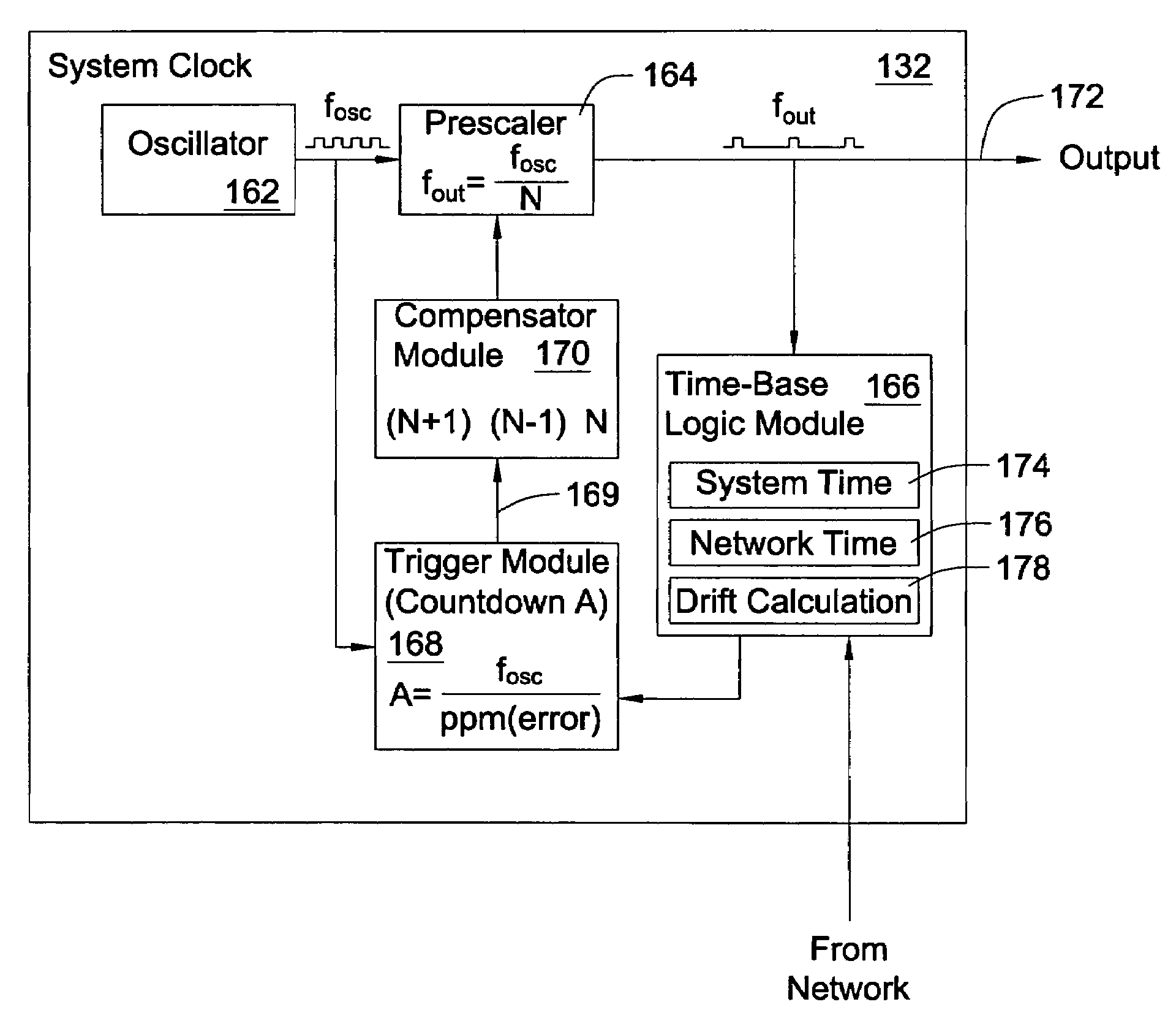
[0009]Consistent with the foregoing, and in accordance with the invention as embodied and broadly described herein, an apparatus for measuring and correcting drift in downhole clocks is disclosed in one aspect of the present invention as including a prescaler configured to receive electrical pulses from an oscillator. The prescaler is configured to output a series of clock pulses. The prescaler outputs each clock pulse after counting a preloaded number of electrical pulses from the oscillator. The prescaler is operably connected to a compensator module for adjusting the number loaded into the prescaler. By adjusting the number that is loaded into the prescaler, the timing may be advanced or retarded to more accurately synchronize the clock pulses with a reference time source. The compensator module is controlled by a counter-based trigger module configured to trigger the compensator module to load a value into the prescaler. Finally, a time-base logic module is configured to calculate the drift of the downhole clock by comparing the time of the downhole clock with a reference time source.

Problems solved by technology

However, due to the complexity, expense, and unreliability of such systems, many attempts to create such a system have failed to achieve significant commercial acceptance.
One problem that has not been adequately addressed involves the time synchronization of downhole components.
Synchronizing the time of downhole devices may be further complicated by the very nature of a downhole environment.
Thus, clocks may gradually drift away from a desired reference time.
This drift is worsened in downhole environments because extreme temperatures, whether hot or cold, often amplify fluctuations in oscillator frequency.
Thus, clocks that provide adequate precision above the surface may be unsuitable in downhole drilling applications.

Method used


Image

  • Apparatus and method for compensating for clock drift in downhole drilling components
  • Apparatus and method for compensating for clock drift in downhole drilling components
  • Apparatus and method for compensating for clock drift in downhole drilling components

Examples


Embodiment Construction

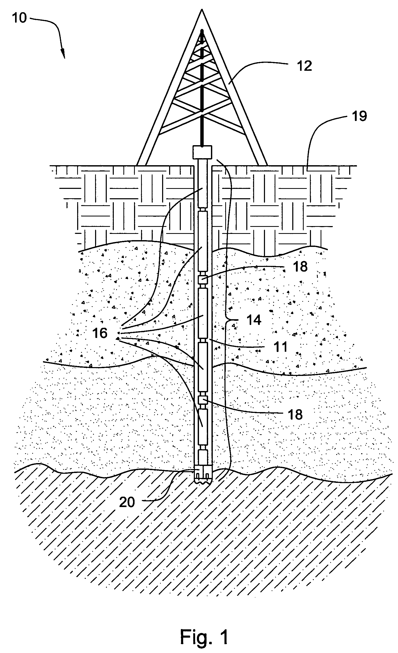
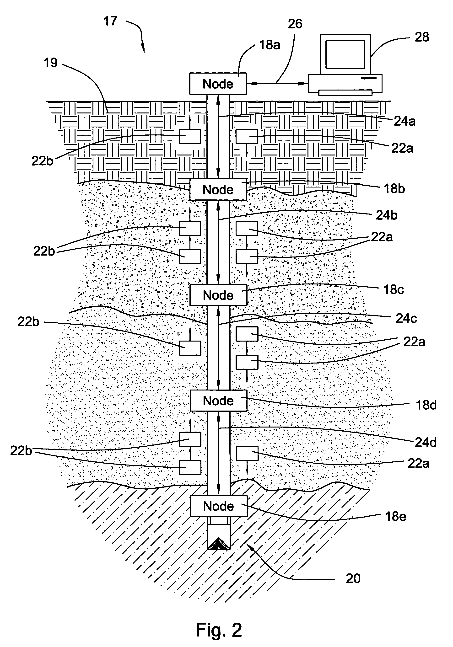
[0023]It will be readily understood that the components of the present invention, as generally described and illustrated in the Figures herein, could be arranged and designed in a wide variety of different configurations. Thus, the following more detailed description of embodiments of apparatus and methods of the present invention, as represented in the Figures, is not intended to limit the scope of the invention, as claimed, but is merely representative of various selected embodiments of the invention.

[0024]The illustrated embodiments of the invention will be best understood by reference to the drawings, wherein like parts are designated by like numerals throughout. Those of ordinary skill in the art will, of course, appreciate that various modifications to the apparatus and methods described herein may easily be made without departing from the essential characteristics of the invention, as described in connection with the Figures.

[0025]Thus, the following description of the Figure...


PUM


Abstract

A precise downhole clock that compensates for drift includes a prescaler configured to receive electrical pulses from an oscillator. The prescaler is configured to output a series of clock pulses. The prescaler outputs each clock pulse after counting a preloaded number of electrical pulses from the oscillator. The prescaler is operably connected to a compensator module for adjusting the number loaded into the prescaler. By adjusting the number that is loaded into the prescaler, the timing may be advanced or retarded to more accurately synchronize the clock pulses with a reference time source. The compensator module is controlled by a counter-based trigger module configured to trigger the compensator module to load a value into the prescaler. Finally, a time-base logic module is configured to calculate the drift of the downhole clock by comparing the time of the downhole clock with a reference time source.

Description

U.S. GOVERNMENT INTEREST[0001]This invention was made with government support under Contract No. DE-FC26-01NT41229 awarded by the U.S. Department of Energy. The government has certain rights in the invention.FIELD OF THE INVENTION[0002]This invention relates to oil and gas drilling, and more particularly to apparatus and methods for compensating for clock drift in downhole drilling components.BACKGROUND[0003]The goal of accessing data from a drill string has been expressed for more than half a century. As exploration and drilling technology has improved, this goal has become more important in the industry for successful oil, gas, and geothermal well exploration and production. For example, to take advantage of the several advances in the design of various tools and techniques for oil and gas exploration, it would be beneficial to have real time data such as temperature, pressure, inclination, salinity, etc. Several attempts have been made to devise a successful system for accessing ...

Claims


Application Information

Patent Timeline
IPC IPC(8): H03K5/01H03K21/00H03K23/52
CPCH03K23/52G01V11/002H04J3/0661
Inventor HALL, DAVID R.PIXTON, DAVID S.JOHNSON, MONTE L.BARTHOLOMEW, DAVID B.HALL, JR., H. TRACY
Owner INTELLISERV
Why Eureka
Try Eureka