Target holder

Inactive Publication Date: 2007-08-14
ODONNELL JAMES
View PDF10 Cites 32 Cited by
  • Summary
  • Abstract
  • Description
  • Claims
  • Application Information

AI Technical Summary

Benefits of technology

[0005]An advantage of the invention resides in an ability of an individual to position a target in order to accurately measure a distance from a first point to a second point throu

Problems solved by technology

This system is completely adequate in open fields where a prism pole may be stuck in the ground however when such a system is used to measure the dimensions of a house or building it may not always be possible to insert the pole into the ground at a location adjac

Method used


Image

  • Target holder
  • Target holder
  • Target holder

Examples


Embodiment Construction

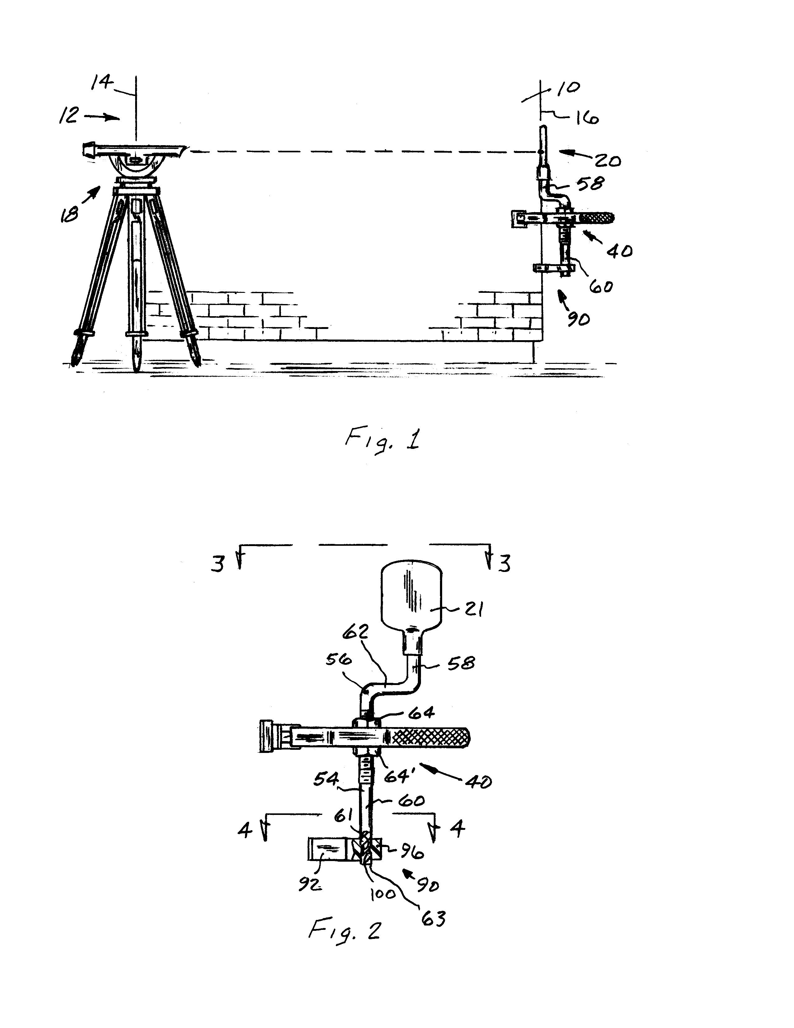
[0013]A wall 10 for building 12 is illustrated in FIG. 1 having a first side 14 and a second side 16. An instrument 18 of a type manufactured by Leica or Stanley that have the capability of directing a laser beam toward a target 20 that is reflected back from the target 20 to measure a distance between the instrument 18 and the target 20. With the instrument 18 set up in a manner as illustrated along side of the wall 10 and perpendicular to the first side 14 a laser beam is directed along a path that is parallel to wall 10 such that the reflected signal when integrated into an electronic control unit (ecu) within the instrument represents an accurate length of the distance between the first side 14 and the second side 16.

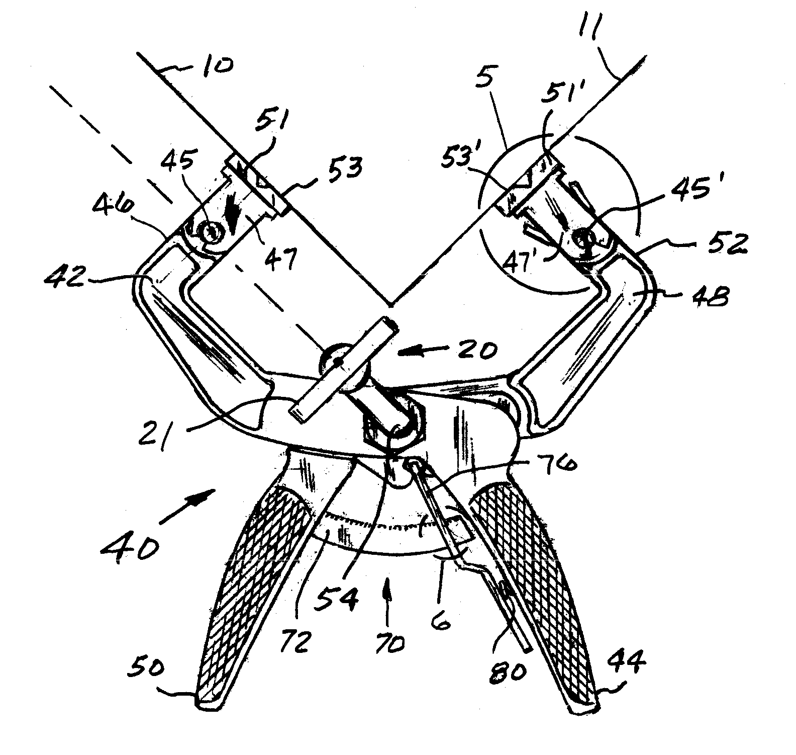
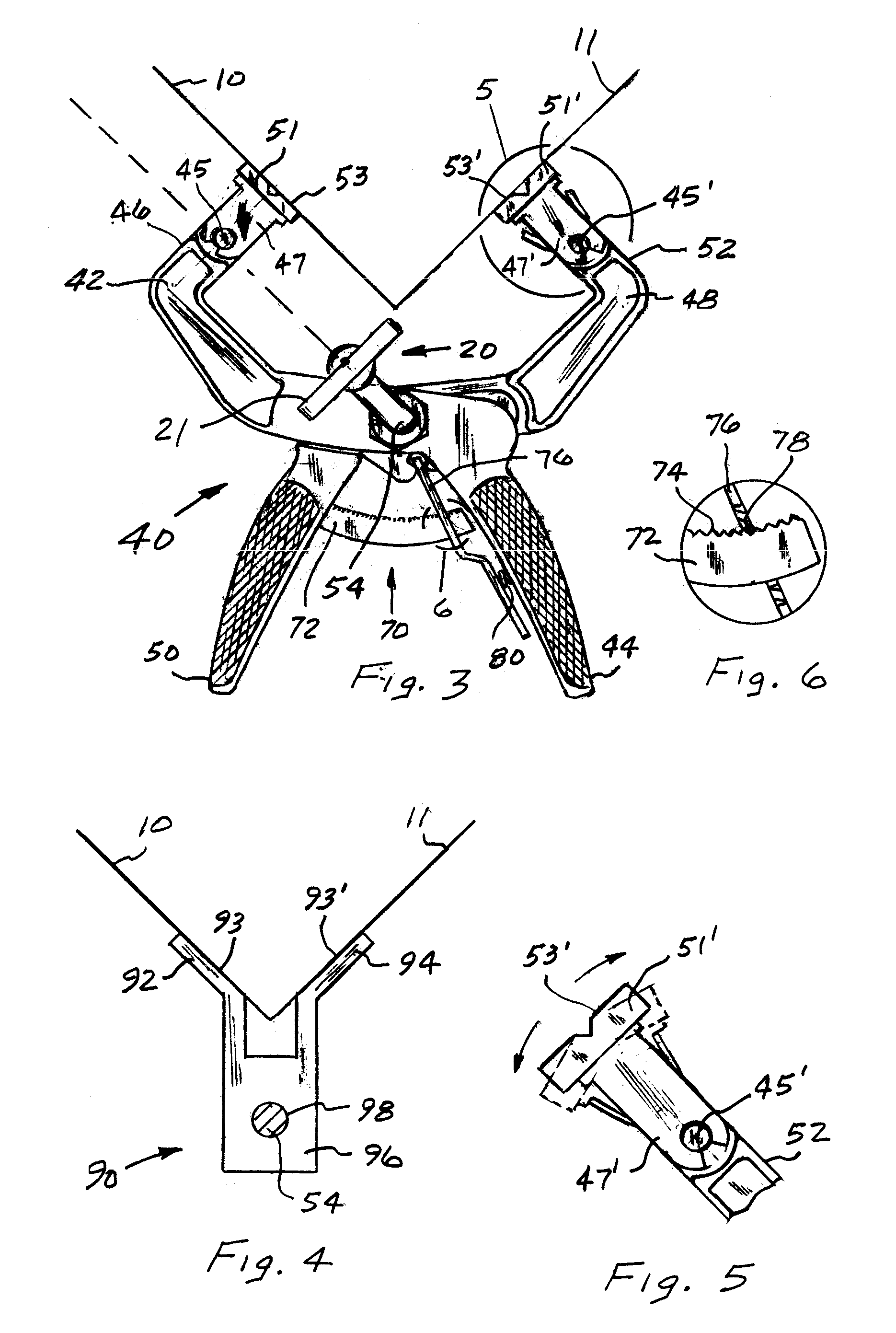
[0014]According to the present invention, the target 20 is located at and held onto a point defined by the intersection of wall 10 with wall 11 by a clamp arrangement 40 that may best illustrated in FIGS. 2 and 3.

[0015]The clamp arrangement 40 is designed such that ...


PUM


Abstract

A device for holding a target adjacent first and second intersecting surfaces of a structure to assist in measuring a distance from an instrument to the target. The device has first and second levers that are joined by a pin that has a section that extends above the levers to receive the target. A force is applied to the first and second levers to bring non-skid pads thereon into engagement with the intersecting surfaces. The target is thereafter rotated into parallel alignment with the second surface and the instrument is aligned with the first surface. A signal transmitted from the instrument is reflected from the target to provide a direct measurement of the distance from the instrument to the target.

Description

[0001]This invention relates to a clamping device for holding a target on a surface of a building to assist in measuring a distance from an instrument to the target.BACKGROUND OF THE INVENTION[0002]In surveying a piece of property it is common for a single operator to use a laser measuring instrument that is positioned at a first location to obtain a distance to a target on a prism pole at a second position. The laser measuring instrument emits a fan-shaped beam to initially locate the target and through a radio system uses a signal that is reflected from a target to calculate the distance and often times an elevation difference with respect to the instrument and the target. This system is completely adequate in open fields where a prism pole may be stuck in the ground however when such a system is used to measure the dimensions of a house or building it may not always be possible to insert the pole into the ground at a location adjacent a side wall due to a sidewalk or the foundati...

Claims


Application Information

Patent Timeline
IPC IPC(8): G01C15/06B25B5/04
CPCB25B5/04B25B5/06B25B5/16B25B5/163G01C15/06
Inventor O'DONNELL, JAMES
Owner ODONNELL JAMES
Why Eureka
Try Eureka