Ultrasonic sensor for detecting the dispensing of a product

a technology of ultrasonic sensor and product, which is applied in the field of ultrasonic sensor, can solve the problems of achieve the effect of boosting the volume of the transmitter and dampening the reception of background ultrasonic nois

Inactive Publication Date: 2007-08-14
CRANE MERCHANDISING SYSTEMS
View PDF16 Cites 19 Cited by
  • Summary
  • Abstract
  • Description
  • Claims
  • Application Information

AI Technical Summary

Benefits of technology

[0010]In further accordance with the preferred form of the invention, the speaker and microphone are housed in separate, axially aligned, cones, preferably formed from plastic. Each cone faces an opposing cone such that sound generated from the speaker housed in a speaker cone reaches the microphone housed in the microphone cone. With this arrangement, the cones focus the ultrasonic signal toward the receiver or microphone unit. Focusing in this manner generally boosts the volume of the transmitter which ultimately dampens the reception of background ultrasonic noise.

Problems solved by technology

Focusing in this manner generally boosts the volume of the transmitter which ultimately dampens the reception of background ultrasonic noise.

Method used


Image

  • Ultrasonic sensor for detecting the dispensing of a product
  • Ultrasonic sensor for detecting the dispensing of a product
  • Ultrasonic sensor for detecting the dispensing of a product

Examples


Embodiment Construction

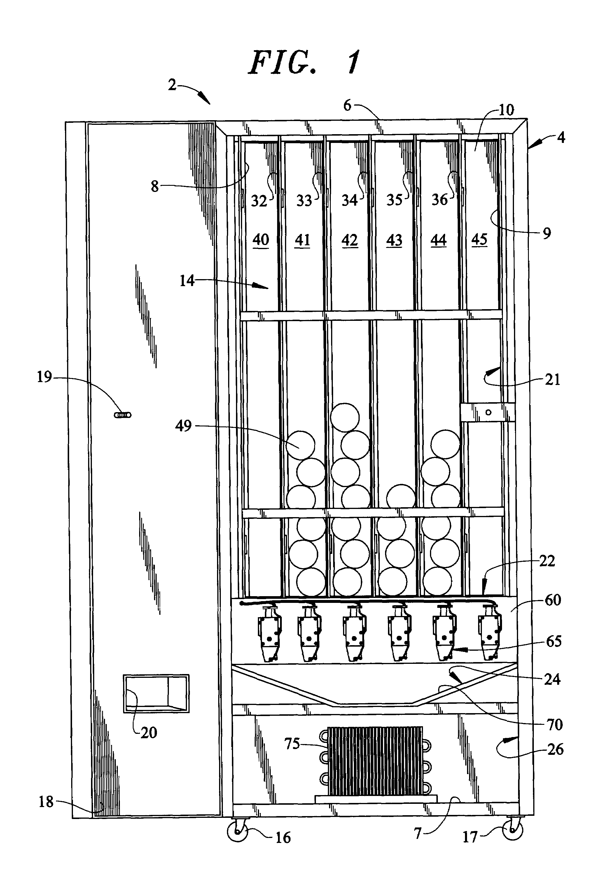
[0017]With initial reference to FIG. 1, a vending machine 2 includes a cabinet frame 4 having top, bottom, side and rear walls 6–10 that collectively define a central cavity 14. In a manner known in the art, a first pair of wheels or casters 16 and 17 are secured to a front edge portion of bottom wall 7 to facilitate the positioning of vending machine 2. Of course it should be realized that a second pair of wheels (not shown) are also arranged on a rear portion of bottom wall 7. A door 18 is pivotally mounted to cabinet frame 4 to selectively enable access to central cavity 14 in order to load various product containers or other commodities into vending machine 2. Door 18 is provided with a locking mechanism, shown in the form of a threaded rod 19, to retain door 18 in a closed position so as to prevent pilfering of the commodities from central cavity 14. Door 18 is also provided with an opening 20 to enable a consumer to remove a vended product container or other commodity from ven...


PUM


Abstract

A vending machine includes a vend sensor for detecting a completion of a vend operation. The vend sensor includes an electronic circuit connected to first and second sound elements positioned on opposing sides of a product delivery chute of the vending machine. The first sound element directs a sound beam across the product delivery chute where it is received by the second sound element. During a vend operation, a product container is guided to the product delivery chute to be dispensed to a consumer. As the container passes through the product delivery chute, the sound beam is interrupted, thereby signaling the completion of a vend operation. Each of the first and second sound elements is provided with a cone that focuses the sound beam so as to limit interruptions stemming from outside sound sources.

Description

CROSS-REFERENCE TO RELATED APPLICATIONS[0001]The present application claims benefit of U.S. Provisional Patent Application Ser. No. 60 / 415,771 entitled “ULTRASONIC SENSOR FOR DETECTING THE DISPENSING OF A PRODUCT” filed on Oct. 4, 2002.BACKGROUND OF THE INVENTION[0002]1. Field of the Invention[0003]The present invention pertains to the art of vending machines and, more particularly, to an ultrasonic sensor for detecting passage of a product container to a delivery portion of the vending machine.[0004]2. Discussion of the Prior Art[0005]Traditional can and bottle vending machines utilize various motors to move mechanisms in the form of cams and the like. In turn, the mechanisms release stored product from within a stack or storage rack arranged within the vending machine. Typically, a consumer inserts currency into a receptacle and thereafter makes a product selection. At this point, a controller operates a delivery mechanism which delivers the selected product to the consumer.[0006]...

Claims


Application Information

Patent Timeline
Patent Type & Authority Patents(United States)
IPC IPC(8): G07F11/10H01L41/00G06F17/00G07F9/02
CPCG07F9/026
Inventor BAUTISTA, DEXTER V.MEINARDI, THOMAS ROGERPOWELL, JOSHUA ROBERT
Owner CRANE MERCHANDISING SYSTEMS
Why Eureka
Try Eureka