

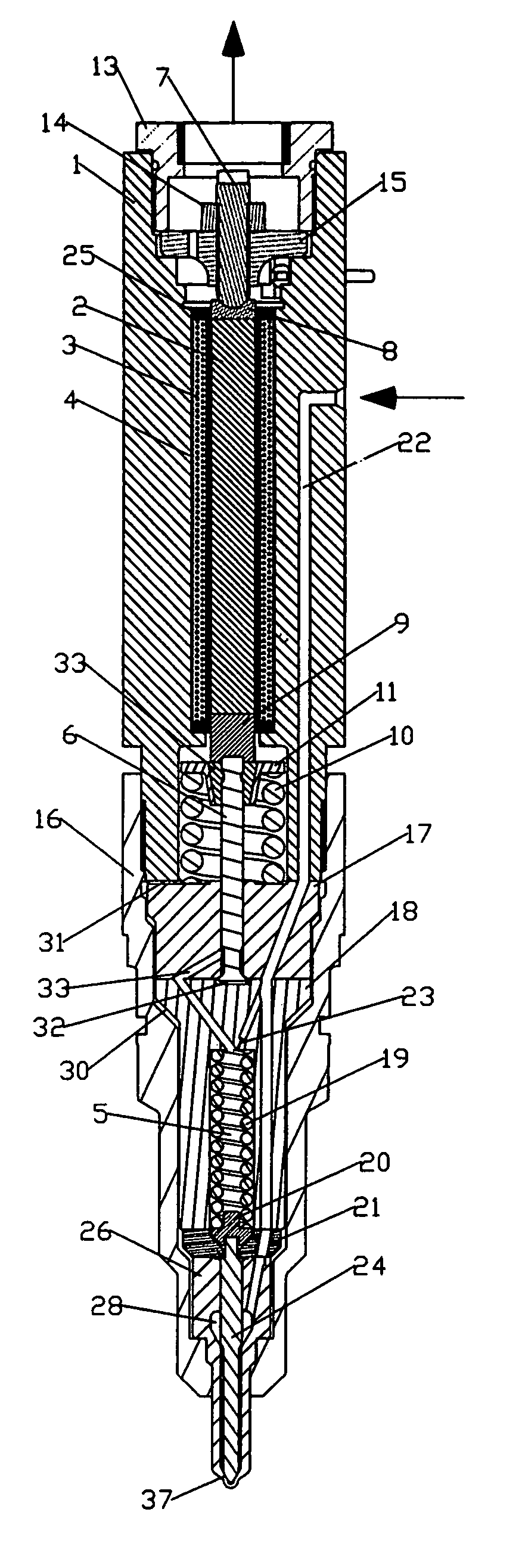
Very high speed rate shaping fuel injector
a fuel injector and high speed technology, applied in the direction of generator/motor, valve operating means/releasing devices, machines/engines, etc., can solve the problems of limited force capability, not a proportional displacement device, and difficult use of solenoid for arbitrary speed rate shaping, so as to minimize the amount of transducing material, reduce fatigue cracking of transducing material, and minimize the effect of diesel particulate matter and oxides of nitrogen formation
- Summary
- Abstract
- Description
- Claims
- Application Information
AI Technical Summary
Benefits of technology
Problems solved by technology
Method used
Image

Examples
Embodiment Construction
[0051]Those of ordinary skill in the art will realize that the following description of the present invention is illustrative only and not in any way limiting. Other embodiments of the inventions will readily suggest themselves to such skilled persons.
[0052]The embodiments disclosed herein were chosen and described in order best to explain the principles of the invention and its practical application, thereby to enable others skilled in the art best to utilize the invention in various embodiments and with various modification as are suited to the particular use contemplated therefor. It is intended that the scope of the invention be defined by the claims appended hereto, when interpreted in accordance with the full breadth to which they are legally and equitably entitled.
[0053]There are many possible hydro-mechanical embodiments of an injector that would take advantage of the almost arbitrary speed made possible by the properly embodied GMM element. The best embodiment will take adv...
PUM
 Abstract
Description
Claims
Application Information