
Bottom-emptying device for tapered bailer

a bottom-emptying device and bailer technology, applied in the field of bailers, can solve the problems of increasing the turbidity of the sample that is collected, introducing insufficient amounts of oxygen into the sample, and turbid samples that are unacceptable for environmental analysis

Inactive Publication Date: 2007-08-14
PRATT DAVID W
View PDF7 Cites 3 Cited by
  • Summary
  • Abstract
  • Description
  • Claims
  • Application Information

AI Technical Summary

Benefits of technology

[0014]The leading end of the bailer is a frusto-conical valve housing that is secured, preferably by welding, to the leading end of the cylindrical main body. The valve housing has a leading end that has a diameter less than its trailing end and the trailing end of the valve housing has a diameter substantially equal to a diameter of the cylindrical main body of the bailer. The valve housing significantly reduces agitation and suppresses turbidity when the bailer is introduced into a body of liquid fluid.
[0017]An important object of this invention is to provide a bailer bottom-emptying device that does not cause a user's hands to come into contact with liquid fluid during the bailer-emptying process.

Problems solved by technology

Common bailers agitate the liquid fluid into which they are dropped, thereby increasing the turbidity of the sample that is collected.
Turbid samples are unacceptable for environmental analysis because the particulate matter contained therein is introduced into the sample by the agitation created by the sample collection process.
Bailers are best emptied from the bottom because unacceptable amounts of oxygen are introduced into the sample if the bailer is decanted from the top.
Various devices have been developed to facilitate bottom-emptying, but the known devices do not perform the emptying process in an optimal manner.
The hands of the person handling the bottom-emptying device are therefore wetted.
If the liquid fluid is highly acidic or otherwise dangerous, use of such a bottom-emptying device is unacceptable, Even if the fluid is not dangerous, the user may not care to get his or her hands wet, especially during cold weather.

Method used


Image

  • Bottom-emptying device for tapered bailer
  • Bottom-emptying device for tapered bailer
  • Bottom-emptying device for tapered bailer

Examples


Embodiment Construction

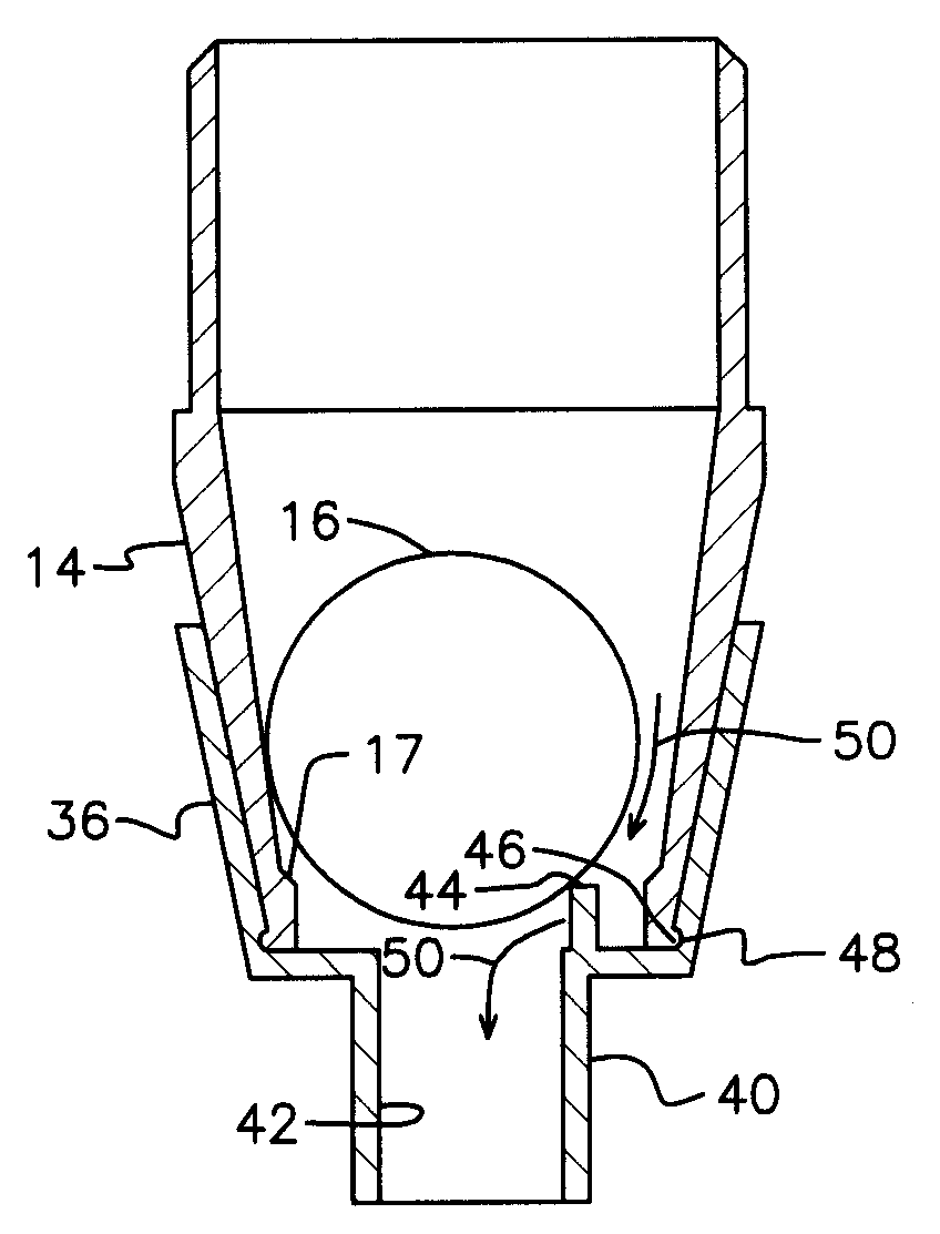
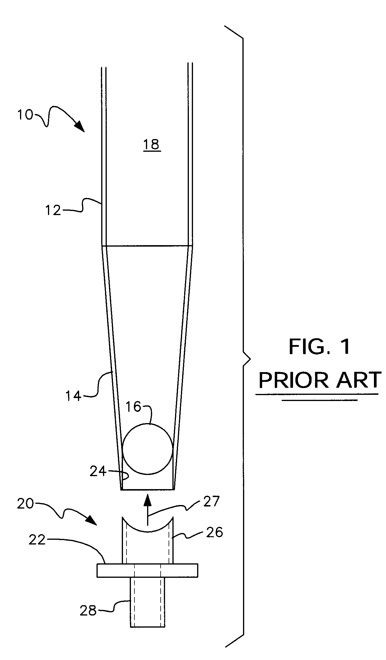
[0033]Referring to the front elevational view of FIG. 1, it will there be seen that the reference numeral 10 denotes a prior art bailer having a cylindrical main body 12 and a leading end having tapered sidewalls 14. Free-floating ball 16 is a check valve. It is unseated to admit liquid fluid into the hollow interior 18 of bailer 10 when the bailer enters into liquid fluid and it is seated to prevent leakage of liquid fluid from said hollow interior when the bailer is retrieved from the liquid fluid.

[0034]Other types of check valves are also within the scope of this invention. For example, see the check valve in U.S. Pat. No. 6,457,486 entitled “Bailer Having Leak-Inhibiting Seal” to the present inventor.

[0035]Prior art bottom-emptying device 20 includes flange 22 that has a diameter greater than that of opening 24 of said leading end 14 to limit the depth of insertion of ball-unseating member 26. Said ball-unseating member 26 has a tubular construction and an outer diameter less th...


PUM

PropertyMeasurementUnit
diameteraaaaaaaaaa
turbidityaaaaaaaaaa
wettingaaaaaaaaaa

Abstract

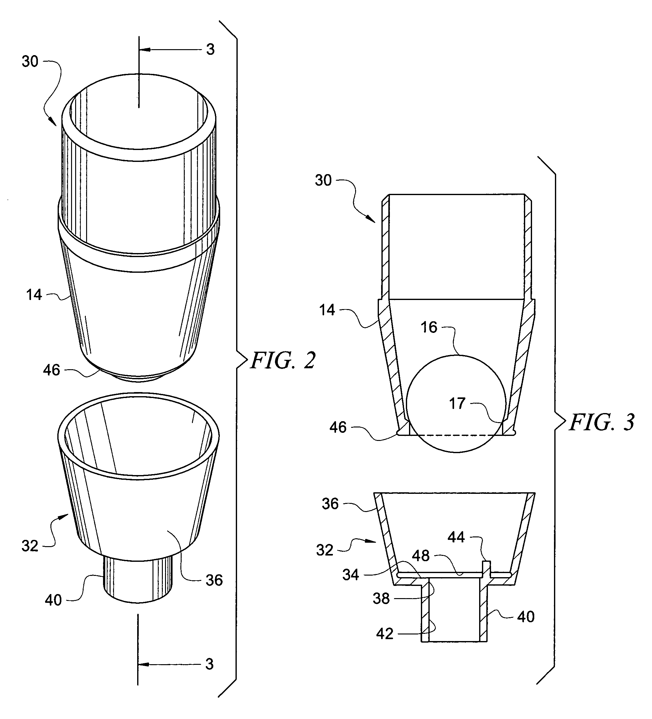
A bailer has a tapered leading end to reduce agitation and turbidity as the bailer is introduced into a body of liquid fluid. A check valve is unseated and admits liquid fluid into the bailer as the bailer enters the liquid fluid. The check valve is seated and seals the liquid fluid within the bailer against leakage when the bailer is retrieved from the liquid fluid. A first embodiment includes a bottom-emptying device that guides liquid fluid in the bailer into a wide-mouth container. A second embodiment includes a bottom-emptying device that guides the liquid fluid into a narrow mouth container such as a vial. In both embodiments, the bottom-emptying device is tapered and engages the outside walls of the tapered leading end of the bailer. This prevents liquid fluid from wetting a user's hands when the bottom-emptying device is used to unseat the check valve.

Description

BACKGROUND OF INVENTION[0001]1. Field of the Invention[0002]This invention relates, generally, to bailers. More particularly, it relates to a bottom-emptying device that engages the outside of a bailer.[0003]2. Description of the Prior Art[0004]Common bailers agitate the liquid fluid into which they are dropped, thereby increasing the turbidity of the sample that is collected. Turbid samples are unacceptable for environmental analysis because the particulate matter contained therein is introduced into the sample by the agitation created by the sample collection process. The collected sample thus does not represent the liquid fluid in the body of water.[0005]A co-pending patent application by the present inventor, entitled “Bailer With Tapered And Ogive Nose Cones,” application Ser. No. 10 / 248,378, filed Jan. 15, 2003, substantially solves the agitation and turbidity problem by providing a bailer having a tapered leading end. The taper allows the bailer to slice into the liquid fluid...

Claims


Application Information

Patent Timeline
Patent Type & Authority Patents(United States)
IPC IPC(8): G01N1/12
CPCG01N1/12
Inventor PRATT, DAVID W.
Owner PRATT DAVID W
Learn More