Dimmer device for backlight module

a backlight module and light distributing technology, which is applied in shaving accessories, lighting and heating apparatus, instruments, etc., can solve the problems of increasing the production cost of diffusers, the complexity of manufacturing processes, and the efficiency of correcting phenomena, so as to improve the structure of light distributing, eliminate the effect of dark bands

Inactive Publication Date: 2007-08-14
K-BRIDGE ELECTRONICS CO LTD
View PDF12 Cites 47 Cited by
  • Summary
  • Abstract
  • Description
  • Claims
  • Application Information

AI Technical Summary

Benefits of technology

[0008]The primary purpose of the present invention is to provide an improved structure of a light distributing device to actively and effectively solve the problems of the significant bright bands and dark bands observed with the LCD module of the prior art to more effectively distribute the lights emitted form the light sources. To achieve this purpose, one or more light distributing devices are disposed between the spaced light sources to evenly diffuse the light diffused from both sides of the light sources towards the diffuser plate after having been properly refracted and reflected, to thereby eliminate the dark bands between any abutted light sources.

Problems solved by technology

Whereas the diffuser plate 30 functions only to help achieve the even diffusion for lights passing through it, it has a limited efficiency in correcting the phenomenon of the bright bands and the dark bands observed on the LCD module.
However, the structural design for such an improvement not only provides limited effects but also causes the backlight module to be thicker thereby making the LCD module too large.
Again, this extinction process not only increases the production cost of the diffuser and the complexity of the manufacturing process, but also only provides a passive solution to reduce the dark bands on the LCD since the extinction is created only after the light lands on the surface of the diffuser.
However, the light distributing 12 integrated with the reflector mask 10 functions only for the purpose of reflective distribution and fails to provide a refractive or diffusive distribution function.

Method used


Image

  • Dimmer device for backlight module
  • Dimmer device for backlight module
  • Dimmer device for backlight module

Examples


Embodiment Construction

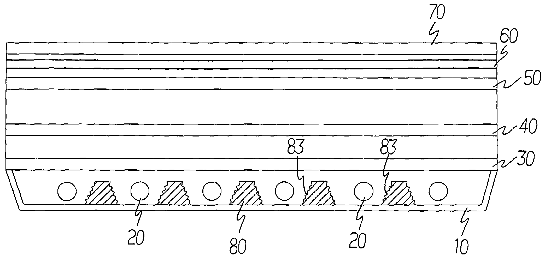
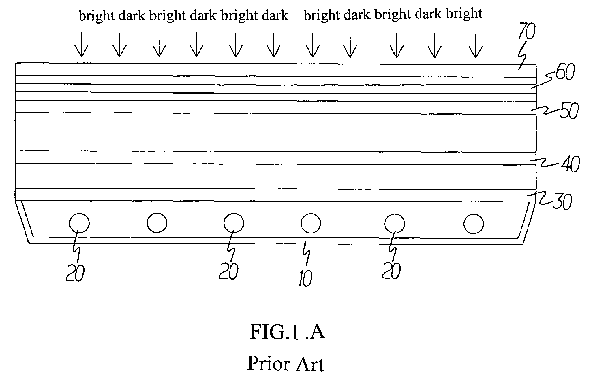
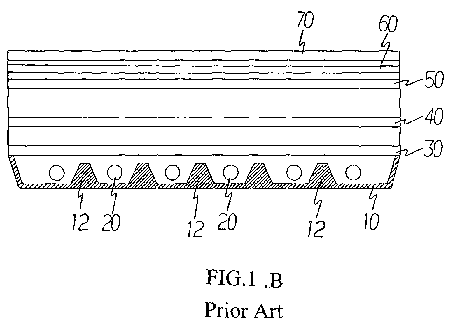
[0019]Referring to FIG. 2, a first preferred embodiment of the present invention is a backlight module having a reflector mask 10, multiple light sources 20, and multiple optical films including a diffuser plate 30, a lower diffuser sheet 40, a prism 50, a reflective polarizing sheet or an upper diffuser 60 in combination with a LCD 70 arranged in sequence from inside out. Wherein, those light sources 20 may be each a light tube in a stripe, U-shape or other continuously curved space. The light sources 20 are preferrably arranged at a proper spacing between the reflector mask 10 and the lower diffuser sheet and the light emitted by each of those light sources 20 provide the display effects on the LCD.

[0020]One or more than one solid or hollow light distributing device 80 is provided in the space between adjacent light sources 20. In a first preferred embodiment of the present invention as illustrated in FIG. 2, the light distributing device 80 is made in a structure bonded to the re...


PUM

PropertyMeasurementUnit
transparentaaaaaaaaaa
brightnessaaaaaaaaaa
U-shapeaaaaaaaaaa

Abstract

At least one light distribution device is provided in the spacing between adjacent light sources to allow light diffused from both sides of the light sources to be properly refracted and reflect so as to more evenly diffuse light toward a diffuser plate and thereby, eliminate the dark bands between adjacent light sources for effectively solving the bright bands and dark bands problem observed in prior art LCD modules.

Description

BACKGROUND OF THE INVENTION[0001](a) Field of the Invention[0002]The present invention is related to an improved structure of a backlight module light distributing device, and more particularly to one that effectively light from light sources without developing bright bands and dark bands.[0003](b) Description of the Prior Art[0004]As illustrated in FIG. 1 (A) of the accompanying drawings for an improved structure of a LCD backlight module of the prior art, the backlight module is essentially comprised of a reflector mask 10, multiple light sources 20, a diffuser plate 30, a lower diffuser sheet 40, a prism 50, a reflective polarizing sheet or an upper diffuser sheet 60 and a LCD 70 arranged in sequence from inside out. Wherein, those light sources 20 may be each a light tube in a stripe, U-shape or other continuous curve. The light sources 20 may be arranged at a proper spacing between the reflector mask 10 and the diffuser plate 30 and the light emitted by each of the light source...

Claims


Application Information

Patent Timeline
Patent Type & Authority Patents(United States)
IPC IPC(8): F21V7/04A45D42/10A47F3/00G01D11/28G02F1/1335G02F1/13357G09F13/00H03H9/00
CPCG02F1/133604G02F1/133606G02F2001/133607G02F1/133607
Inventor TSENG, WEN-PAO
Owner K-BRIDGE ELECTRONICS CO LTD
Why Eureka
Try Eureka