
Motor or generator and method of producing the same

a technology of motors and generators, applied in the direction of windings, dynamo-electric components, magnetic circuit shapes/forms/construction, etc., can solve the problems of complex configuration of stator cores, limited coils to concentrated windings, and increased labor for winding operations, so as to achieve simple coil operation, large-scale equipment, and high cost

Inactive Publication Date: 2007-08-14
TOYOTA IND CORP
View PDF7 Cites 5 Cited by
  • Summary
  • Abstract
  • Description
  • Claims
  • Application Information

AI Technical Summary

Benefits of technology

This method simplifies the coil formation process, increases the lamination factor of conductor wires, and enhances the efficiency of rotating electrical units by allowing for wave winding configurations without the requirement of expensive or large-scale devices.

Problems solved by technology

In a case where a coil is formed by winding a conductor wire directly around a slot provided at a stator core (especially, in a case where a slot is provided on an inner circumference side of a cylindrical stator core), the labor for a winding operation increases.
According to the method described in patent document 1, however, it is interpreted that the configuration of a stator core is complicated and the coil is limited to a concentrated winding.
In the insert method described in the patent document 2, an inserter itself is a relatively large-scale and also expensive device.

Method used


Image

  • Motor or generator and method of producing the same
  • Motor or generator and method of producing the same
  • Motor or generator and method of producing the same

Examples


Embodiment Construction

[0032]The following is the explanation of the embodiment of the present invention in reference to the drawings. The explanation is made for the case where the present invention is applied to a synchronous machine as a rotating electrical unit. Here, the rotating electrical unit of the embodiment includes a stator and a rotor each functioning as an armature similarly to a general rotating electrical unit, but the configuration of the rotor is not characteristic. Therefore, the configuration of the rotor is omitted. Incidentally, steps other than the step of producing a stator may be realized by a general technology or a publicly known technology.

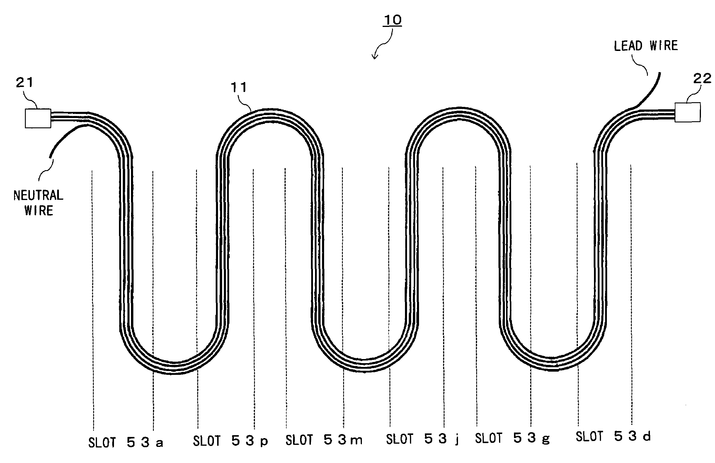
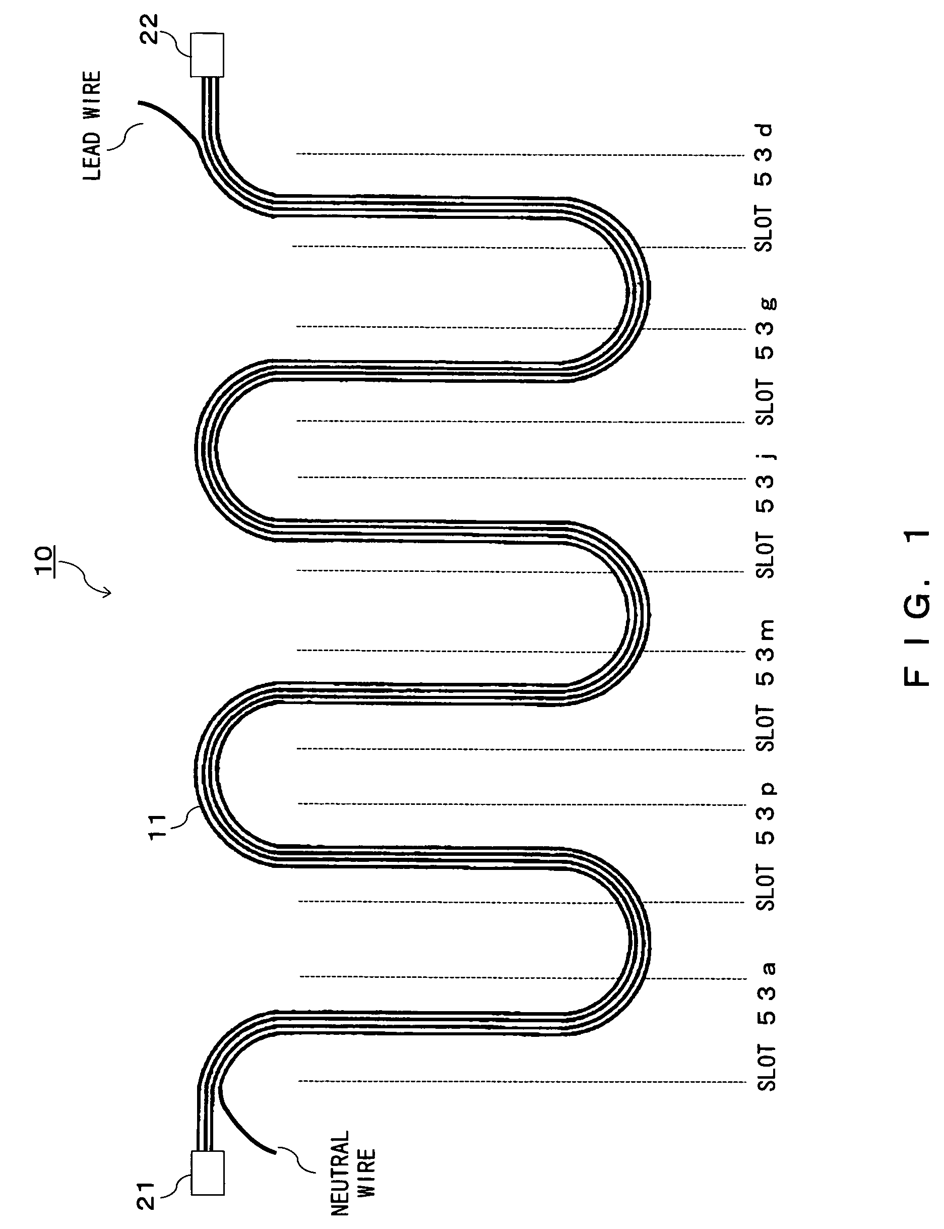
[0033]FIG. 1 is a pattern diagram showing a cable component used as a coil in a rotating electrical unit of the embodiment. Meanwhile, the rotating electrical unit of the embodiment includes a motor and a generator. The following is the explanation of the case where the rotating electrical unit is a three-phase rotating electrical unit and th...


PUM


Abstract

A plurality of slots is provided at a stator core. A cable component is formed by bundling a plurality of conducting wires and connectors are mounted on both ends. The cable component is inserted into corresponding slot so as to cross over the corresponding plurality of slots and then a coil is formed by connecting both ends of the cable component.

Description

BACKGROUND OF THE INVENTION[0001]1. Field of the Invention[0002]The present invention relates to a motor and a generator of which the armature is wound by a coil and also relates to a method thereof.[0003]2. Description of the Related Art[0004]A rotating electrical unit has been conventionally and widely used in various fields. Here, the rotating electrical unit includes a motor and a generator. The use of the rotating electrical unit is not limited but here it is used as, for example, a motor for driving the compressor of an air conditioner, a motor for running an electric vehicle (including a hybrid car), a generator mounted on a car, etc.[0005]The rotating electrical unit is generally provided with a coil for generating a magnetic field (in the case of a generator, a coil for generating electromotive force in accordance with the change of a flux). The following method is well known as a method of forming a conventional wire.[0006]For example, in a rotating electrical unit describ...

Claims


Application Information

Patent Timeline
Patent Type & Authority Patents(United States)
IPC IPC(8): H02K11/00H02K1/18H02K3/04H02K3/12H02K3/28H02K3/32H02K3/50H02K15/04H02K15/06
CPCH02K3/12H02K3/50H02K15/0435H02K15/06H02K2203/15H02K15/0478
Inventor FUKASAKU, HIROSHIUETSUJI, KIYOSHI
Owner TOYOTA IND CORP
Learn More