Keeper circuits having dynamic leakage compensation

a technology of dynamic leakage compensation and keeper circuit, which is applied in logic circuits, logic functions, pulse techniques, etc., can solve the problems of significant limits on the circuit design of digital dynamic circuits, particularly register files and multi-port srams, and achieve uniform and predictable effects on evaluation times

Active Publication Date: 2007-08-14
FUJITSU LTD
View PDF11 Cites 42 Cited by
  • Summary
  • Abstract
  • Description
  • Claims
  • Application Information

AI Technical Summary

Benefits of technology

[0006]The present invention eliminates the above limitation by coupling a current-setting transistor in series with the keeper transistor, with the current-setting transistor setting the maximum current flow through its conduction terminals to a level that is related to the leakage current level of the transistors in the pull-down logic circuit. The keeper transistor may thereby be designed to have a higher conductance than that of the current-setting transistor since its maximum current is set by the current-setting transistor. When the keeper transistor is enabled, the total current flowing through it and the current-setting transistor can be made to substantially track the leakage current, despite process variations, and even temperature variations. Either the keeper transistor or the current-setting transistor may be coupled to the intermediate node. In a set of preferred embodiments, the maximum current flow through the current-setting transistor is limited to an estimate of the sum of the maximum leakage currents through the legs of the NMOS logic circuit plus a safety margin, such as 10% to 1000% of the estimated sum of the leakage currents. In these preferred embodiments, the estimate of the sum of the maximum leakage currents is preferably generated from a sensing network that comprises at least one NMOS transistor located near the NMOS pull-down transistors of the logic circuit. As explained in greater detail below, the sensing network may be configured in a number of ways. In these preferred embodiments, the leakage current of the sensing network may be measured and scaled by two PMOS transistors configured in a current-mirror topology, with the controlled mirror transistor being used as the current-setting transistor. Thus, in this manner, the maximum current through the keeper transistor is set to a value that is related to the leakage current of the adjacent NMOS pull-down transistors, and is automatically adjusted to account for variations in the leakage current caused by manufacturing variations. Furthermore, the current-mirror topology minimizes the effects that variations in the PMOS-transistor characteristics have on the maximum current value of the current-setting transistor.
[0012]Accordingly, it is an object of the present invention to enable keeper circuits to be used in dynamic digital gates implemented with transistor gate lengths of less than 0.1 μm to enable an increase in the maximum number of pull-down legs (or pull-up legs) in the logic circuits of the gates.
[0013]It is a further object of the present invention to provide keeper circuits that have uniform and predictable impacts on the evaluation times of digital dynamic gates despite a wide range of variations in transistor characteristics due to manufacturing variations.
[0014]It is a further object of the present invention to enable large memory devices to be built without impact on access speed by enabling addressing gates to be constructed with more than sixteen pull-down legs.
[0015]It is another object of the present invention to provide keeper circuits for analog circuit applications that have uniform and predictable impacts on the analog circuits despite a wide range of variations in transistor characteristics due to manufacturing variations.

Problems solved by technology

Specifically, it was discovered that conventional keeper circuits effectively limit the number of pull-down legs in the pull-down logic circuit to approximately eight (8), which significantly limits the circuit design of digital dynamic circuits, particularly register files and multi-port SRAMs.
This causes variations in the leakage currents and sinking currents of the NMOS pull-down transistors, and variations in the supply currents of the PMOS keeper transistors.

Method used


Image

  • Keeper circuits having dynamic leakage compensation
  • Keeper circuits having dynamic leakage compensation
  • Keeper circuits having dynamic leakage compensation

Examples


Embodiment Construction

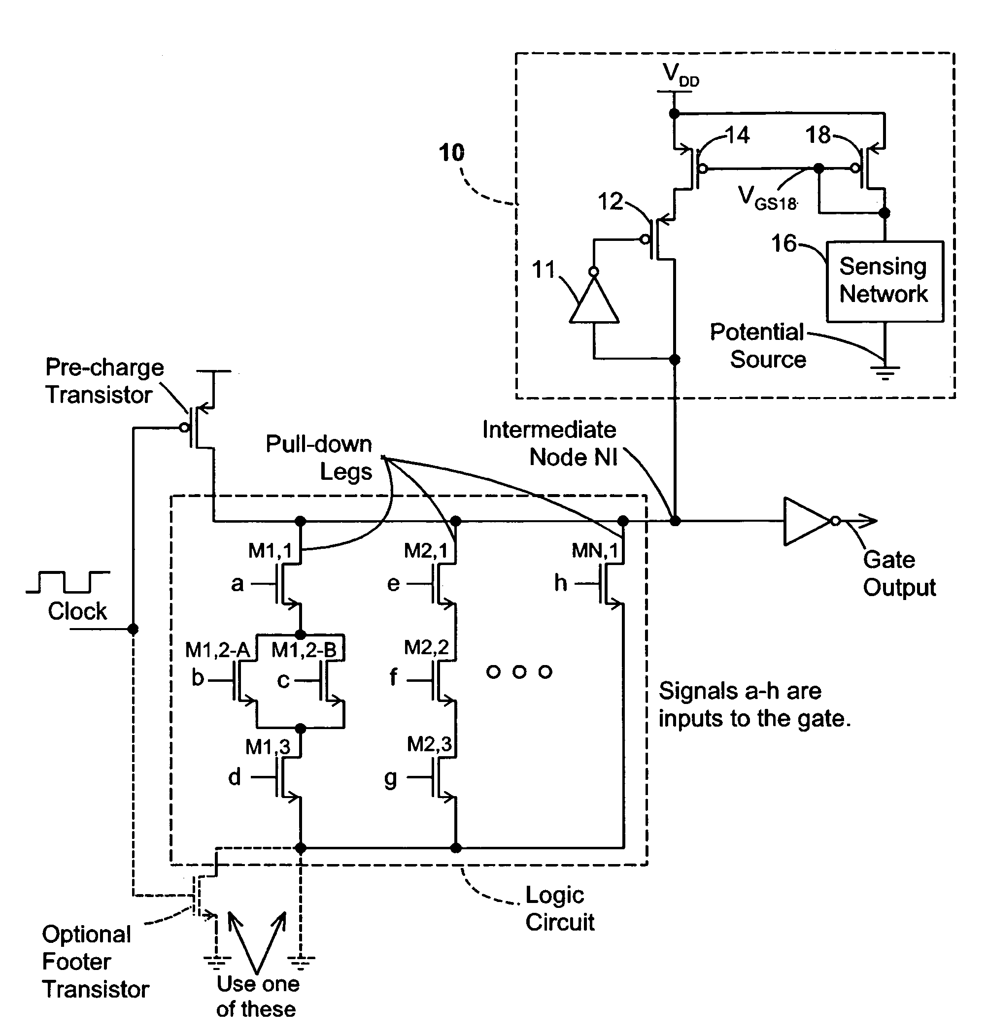
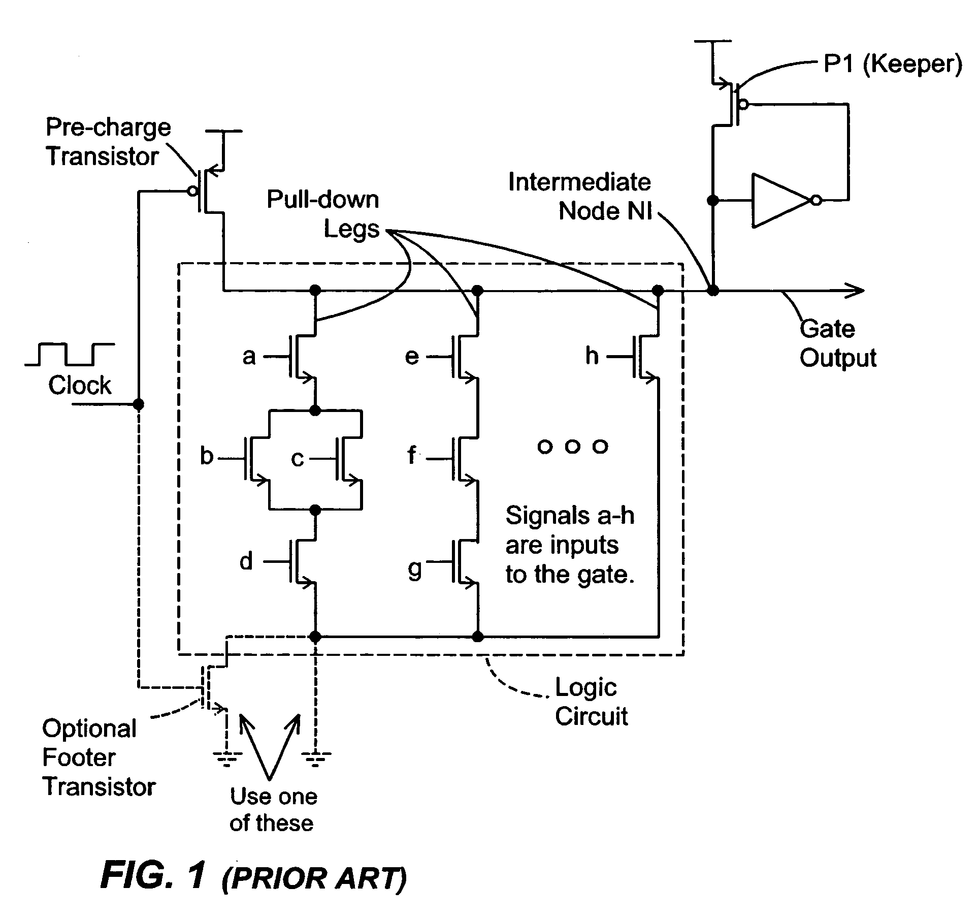
[0026]Dynamic Domino CMOS circuits have been widely used because they offer faster circuit operation compared to static circuits. A conventional dynamic gate, as shown in FIG. 1, employs a keeper transistor P1 that is designed to compensate for leakage current in the NMOS transistors of the pull-down logic circuit. This keeper transistor is needed to prevent the intermediate node NI from being inadvertently discharged to ground by the leakage current in the event that all inputs a-h remain at “0” during evaluation of the function. The on-conductance of keeper transistor P1 is typically a small fraction of the on-conductance of any of the legs in the logic circuit, otherwise the logic delay will be impaired roughly proportionate to the ratio of the on-conductances. (The pre-charge transistor and the optional footer switch are part of the dynamic gate and do not form part of the present invention. If the footer switch is not used, a conductive short to the second supply line is used.)...


PUM


Abstract

Disclosed are keeper circuits for electronic circuits that selectively maintain the voltage level of an intermediate circuit node at a desired level. In one exemplary embodiment, a keeper transistor either provides current or drains current from the intermediate node to maintain the desired voltage level in response to a signal to do so. The keeper circuit works against a leakage current that either drains current from the node or supplies current to the node. A current-setting transistor is coupled in series with the keeper transistor to set the maximum current through the keeper circuit to a value that is related to this leakage current, preferably tracking the leakage current. With this construction, the current-setting transistor is able to track variations in the leakage current caused by variations in the manufacturing process, and thereby provide dynamic leakage compensation.

Description

FIELD OF THE INVENTION[0001]The present invention relates to keeper circuits that may be used in electronic circuits to maintain selected voltage levels, and more particularly to keeper circuits that may be used in digital dynamic logic circuits to maintain selected voltage levels corresponding to selected digital logic values.BACKGROUND OF THE INVENTION[0002]Electronic digital gates can be generally divided into two classes: static gates and dynamic gates. In a static digital gate, the transistors are configured so as to maintain the state of the gate's output until one or more of the inputs to the gate change. CMOS static gates generally have slow pull-up times at their outputs due to the lower conductance of the PMOS devices. In a typical dynamic digital gate (FIG. 1), an intermediate node is pre-charged by a pull-up PMOS transistor during a first phase of a clock signal, and then selectively discharged by a pull-down logic circuit during a second subsequent phase of the clock si...

Claims


Application Information

Patent Timeline
Patent Type & Authority Patents(United States)
IPC IPC(8): H03K19/20
CPCH03K19/0013H03K19/0963
Inventor LIH, YOLINWALKER, WILLIAM W.
Owner FUJITSU LTD
Why Eureka
Try Eureka