High voltage switching apparatus

a switching apparatus and high-voltage technology, applied in the direction of pulse technique, process and machine control, instruments, etc., can solve the problems of single-cost and very bulky load capacitors, and achieve the effect of avoiding stray capacitances in the stack and ensuring the voltage at each switch is more closely controlled

Inactive Publication Date: 2007-08-14
E2V TECH (UK) LTD
View PDF13 Cites 20 Cited by
  • Summary
  • Abstract
  • Description
  • Claims
  • Application Information

AI Technical Summary

Benefits of technology

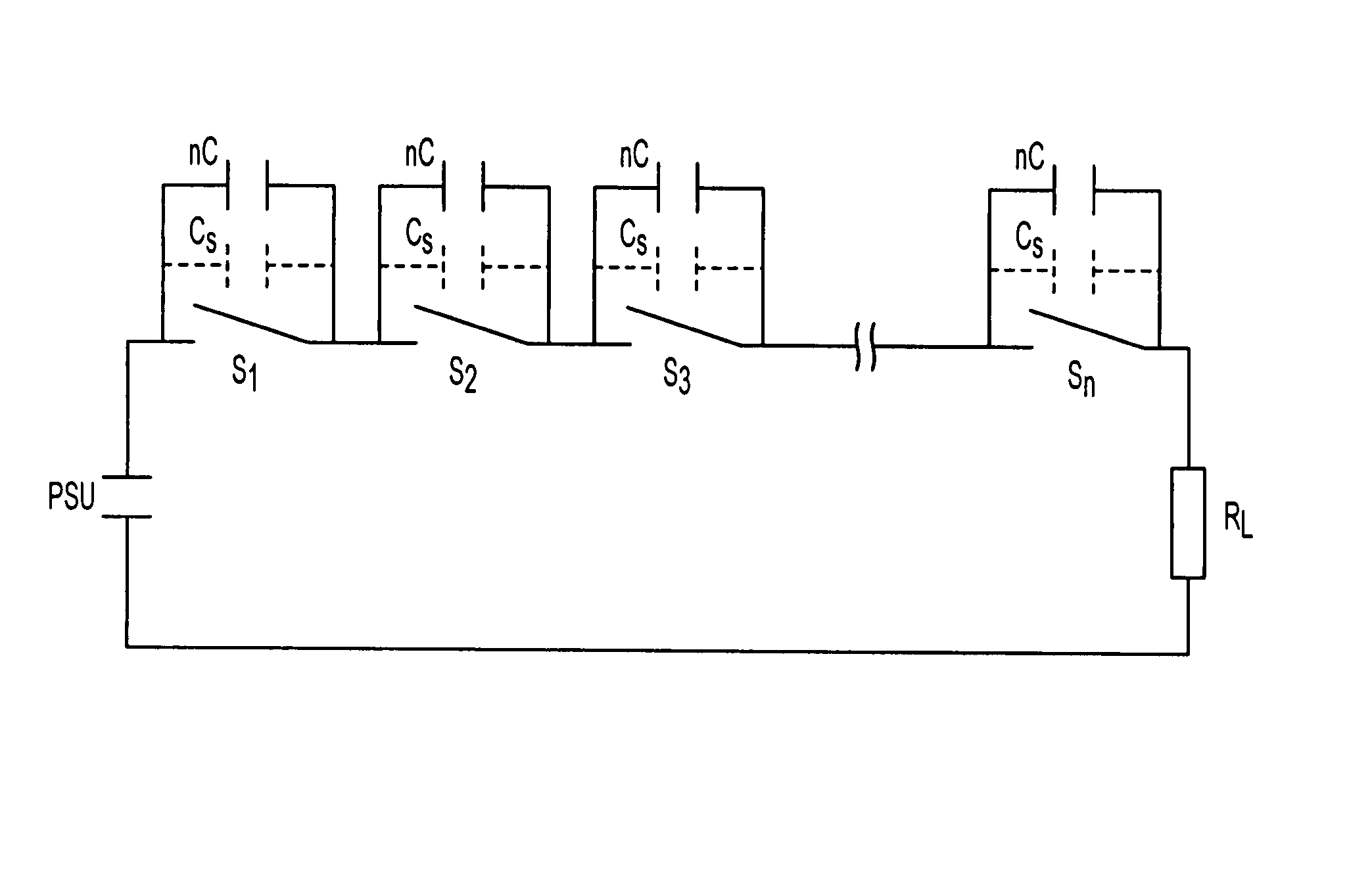
[0009]By arranging a capacitance nC, where n is the number of switches, across each switch in the switch stack, the effects of stray capacitances in the stack are avoided as the stray capacitances are swamped. This enables the voltage at each switch to be more closely controlled which is advantageous. Furthermore, the arrangement enables small cheap capacitors to be used with the switches instead of a single expensive and very bulky load capacitor.

Problems solved by technology

Furthermore, the arrangement enables small cheap capacitors to be used with the switches instead of a single expensive and very bulky load capacitor.

Method used


Image

  • High voltage switching apparatus
  • High voltage switching apparatus
  • High voltage switching apparatus

Examples


Embodiment Construction

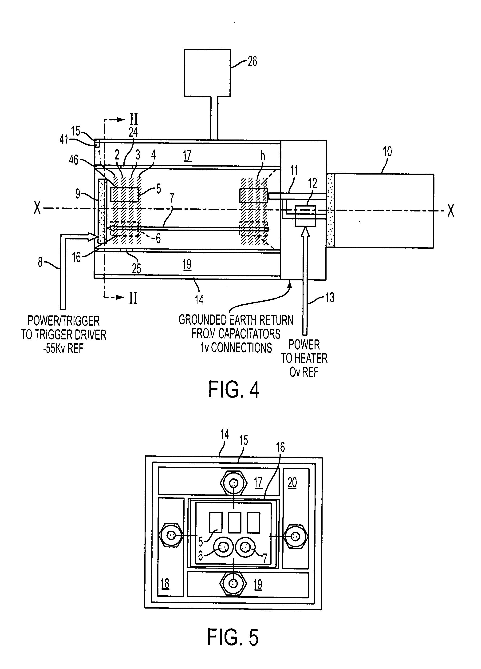
[0018]FIGS. 4 and 5 show the switching mechanism disclosed in our earlier applications GB9928074.5 and GB9928049.7. The mechanism provides high voltage pulses to a high voltage load, such as a magnetron, by switching a capacitance. The switching is triggered by trigger pulses derived from a high voltage supply and the capacitance is also charged by that supply.

[0019]The switching arrangement shown in FIGS. 4 and 5 comprises a switch stack arranged within a chamber surrounded by a plurality of capacitances. The switch stack comprises a number of FET modules 1, 2, 3, 4, . . . n, each of which includes one or more FET switches. There may be, for example, 75 FET modules in the stack and each module may include three FET switches arranged in parallel. The modules are mounted in close proximity to one another and are stacked along the axis in FIG. 1. As well as the FET switch, each module includes a secondary transformer winding 6 with a common primary winding 7 extending along the length...


PUM


Abstract

A switching arrangement for a high voltage load provides high voltage pulses to the load. The switching arrangement includes switching modules, where n is typically (75). A load capacitance is Cd is required to avoid voltage overshoot at the load and is provided by a capacitance of nCd arranged in parallel with each switch.

Description

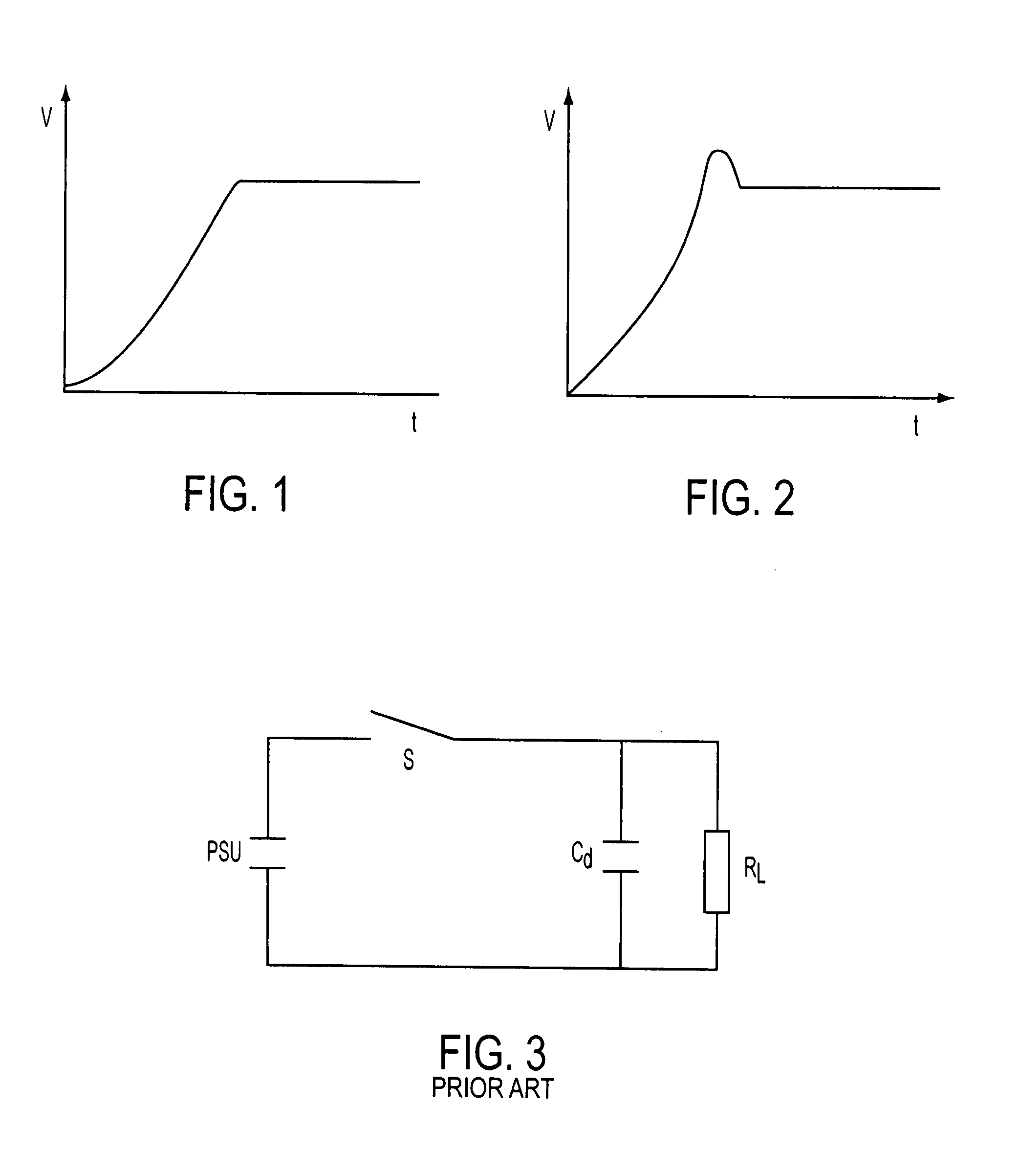
BACKGROUND OF THE INVENTION[0001]1) Field of the Invention[0002]This invention relates to high voltage switching apparatus, and in particular, but not exclusively to a switching apparatus for providing pulses to a pulse switched load.[0003]2) Description of Related Art[0004]Our UK patent applications GB9929074.5 and GB9928049.7 describe a pulsed switching apparatus for an eht load such as a magnetron. A stack of FET switch modules are arranged in an oil filled chamber surrounded by four capacitors which are mounted within a plastics housing. The switch stack receives an eht supply, typically at about −55 kv and delivers a series of eht pulses to the magnetron. The switch also includes various control circuitry which operates at lt voltages. This circuitry controls functions such as triggering of the FET switches.[0005]In these devices, when the load is switched, it is desirable for the voltage to rise smoothly to the operating voltage as shown in FIG. 1. In practice, however, there ...

Claims


Application Information

Patent Timeline
Patent Type & Authority Patents(United States)
IPC IPC(8): H03K17/16H01J23/34H02M9/04H03K3/57H03K17/10
CPCH03K17/102H03K3/57
Inventor ISKANDER, STEPHEN MARKRICHARDSON, ROBERTGOOCH, PAUL ANDREW
Owner E2V TECH (UK) LTD
Why Eureka
Try Eureka