Low-loss rectifier with shoot-through current protection

a technology of shoot-through current and rectifier, which is applied in the direction of electrical equipment, emergency protection circuit arrangements, substation/switching arrangement details, etc., can solve the problems of causing potentially damaging current spikes in input current, relatively large stress on mosfet devices, and at least one of the simultaneously conducting mosfets to be damaged, etc., to achieve low power loss

Inactive Publication Date: 2007-12-06
HARRIS CORP
View PDF12 Cites 17 Cited by
  • Summary
  • Abstract
  • Description
  • Claims
  • Application Information

AI Technical Summary

Benefits of technology

[0007]The invention concerns a transistor active bridge circuit. The transistor active bridge circuit rectifies domestic AC mains (for example, 120V, 60 Hz) and / or foreign AC mains (for example, 230V, 50 Hz) with low power loss. The circuit is connectable between a pair of input lines and a pair of output lines. The transistor active bridge circuit includes first and second field effect transistors of a first channel type. A source-drain path of the first field effect transistor is connected in series with a source-drain path of the second field effect transistor. The series connected transistor pair form a first series transistor combination that is connected across the input lines. The transistor active bridge circuit also includes third and fourth field effect transistors of a second channel type, different from the first channel type. A source-drain path of the third field effect transistor is connected in series with a source-drain path of the fourth field effect transistor to form a second series transistor combination connected across the input lines. A first one of the output lines can be connected to the first series combination at an interconnection point between the first and the second field effect transistors. A second one of the output lines can be connected to the second series combination at an interconnection point between the third and fourth field effect transistors.
[0009]Applying voltage to the active bridge circuit will cause current to flow through the forward biased body diodes of the field effect transistors. This current generates a voltage at the bias voltage tap when it flows through the voltage divider circuit. The voltage derived from the bias voltage tap is used for biasing each transistor to an “on” state in which current can flow between the drain and source. Turning on the field effect transistor shorts the body diode, leaving only a small resistance between the drain and source as current flows through a conductive channel formed by the transistor. The voltage divider circuit also ensures that the voltage between the gate and the source is reduced relative to the input voltage. This ensures operation of the transistor active bridge circuit over a wider range of input voltages without risk of damage to the transistors. In this regard, the transistor active bridge circuit can also include a zener diode connected between the gate and the source of each respective one of the field effect transistors. The zener diode can be provided to serve as a further means for ensuring that the voltage between the gate and source terminals is limited.

Problems solved by technology

However, rectification of an AC mains signal with a MOSFET type bridge rectifier can create potentially damaging current spikes in an input current.
This current spike causes a relatively large amount of stress on the MOSFET devices.
As a result, at least one of the simultaneously conducting MOSFETs can be damaged.

Method used


Image

  • Low-loss rectifier with shoot-through current protection
  • Low-loss rectifier with shoot-through current protection
  • Low-loss rectifier with shoot-through current protection

Examples


Embodiment Construction

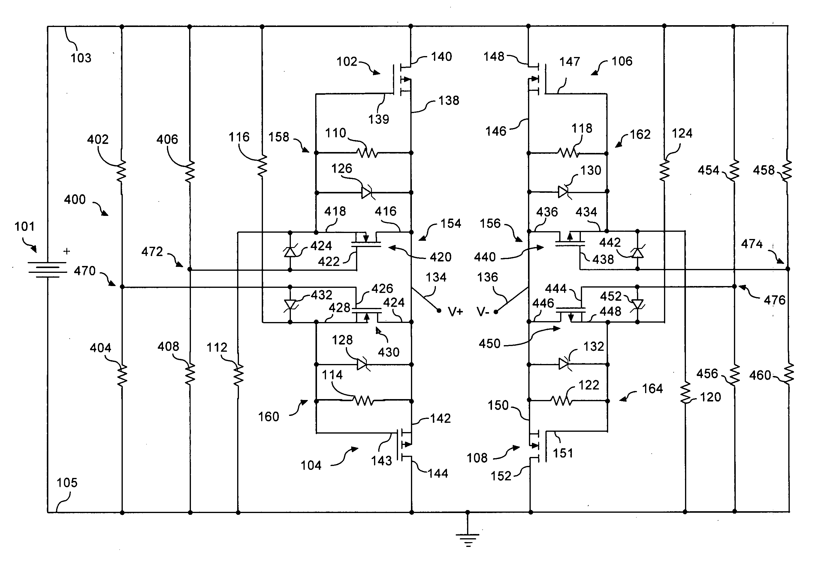
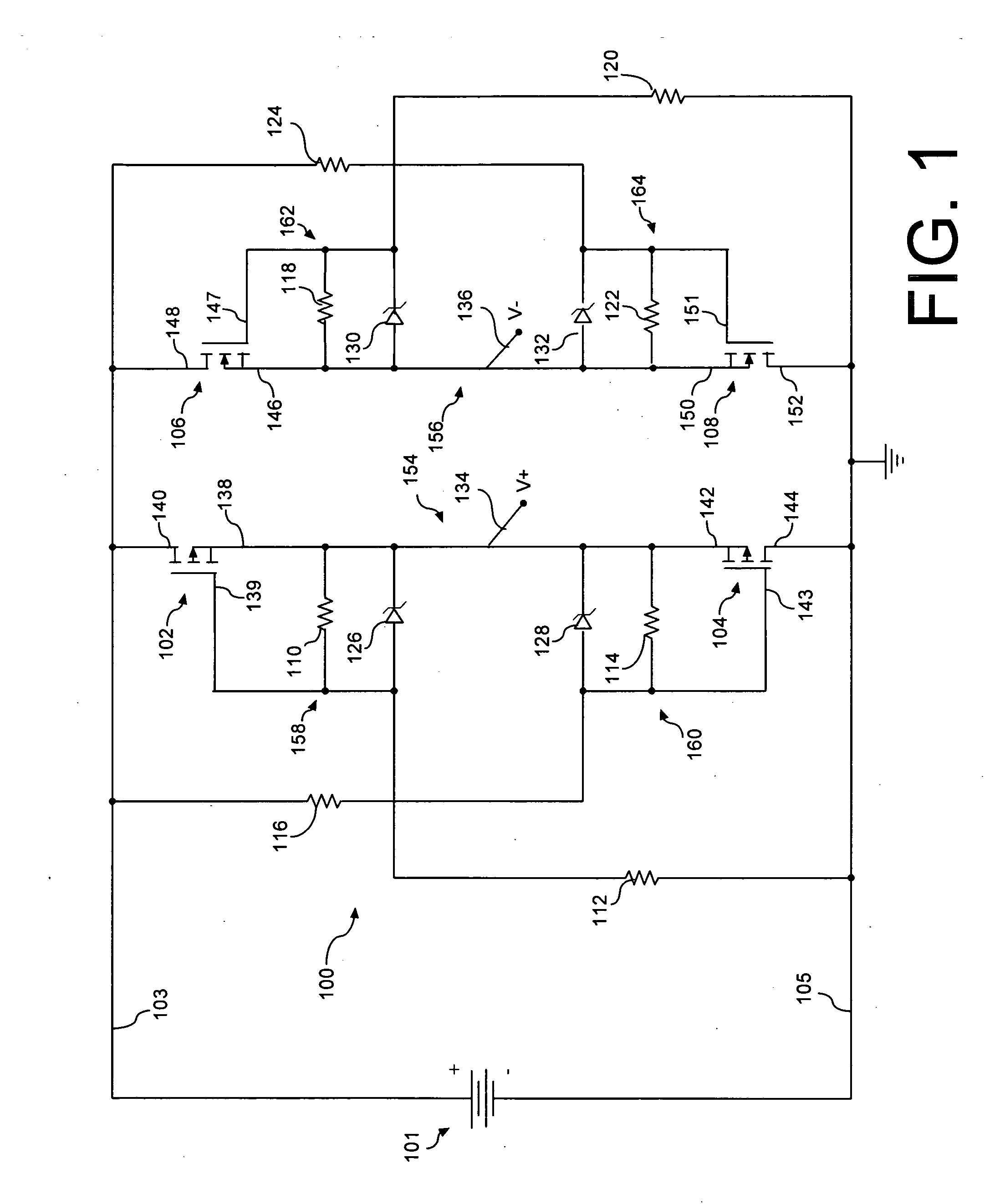
[0019]A transistor active bridge circuit 100 is shown in FIG. 1. The circuit 100 shown is useful for a variety of purposes, including rectification of domestic AC mains (for example, 120V, 60 Hz) and / or foreign AC mains (for example, 230V, 50 Hz) with low power loss. As may be observed in FIG. 1, circuit 100 is connectable between a pair of input lines 103, 105 and a pair of output lines 134, 136.

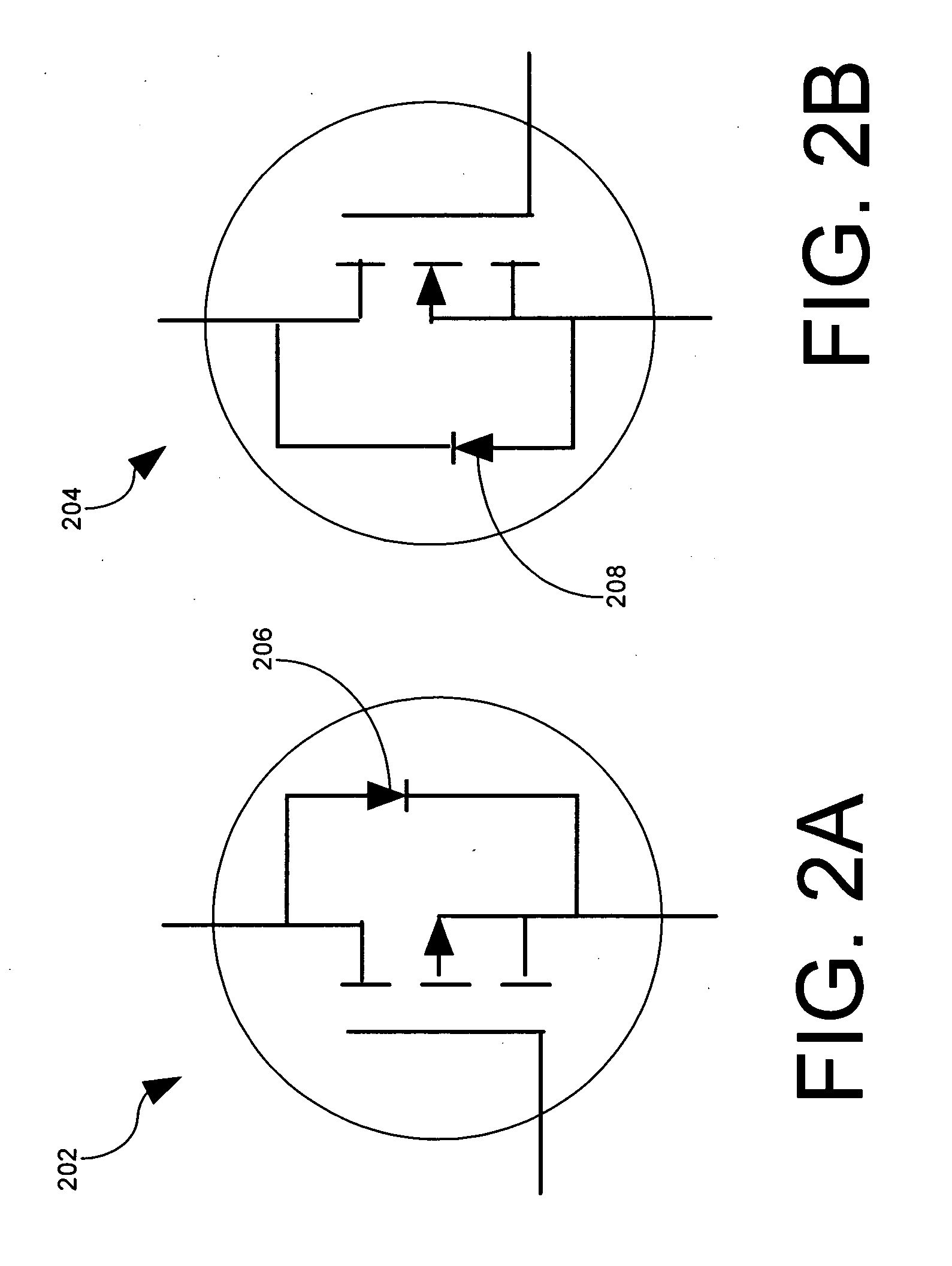
[0020]Circuit 100 includes first and second field effect transistors 102, 104 of a first channel type. The transistor active bridge circuit also includes third and fourth field effect transistors 106, 108 of a second channel type that is different from the first channel type. For example, the first and second field effect transistors 102, 104 can be P-channel type whereas the third and fourth field effect transistors 106, 108 can be N-channel type. Each of the field effect transistors can be enhancement mode devices. For example, the P-channel type transistor can be model number Si7431DP, w...


PUM


Abstract

A transistor active bridge circuit (400) rectifies domestic AC mains (for example, 120V, 60 Hz) and / or foreign AC mains (for example, 230V, 50 Hz) with low power loss. The circuit includes first and second field effect transistors (102, 104) of a first channel type, and third and fourth field effect transistors (106, 108) of a second channel type that is different from the first channel type. A set of voltage dividers (110, 112, 114, 116, 118, 120, 122, 124) and voltage clamping devices (126, 128, 130, 132) permit the circuit (400) to efficiently operate over a wider range of input voltages, without potential damage to the field effect transistors. Shoot-through protection devices (420, 430) provide a means for preventing the first and second field effect transistors (102, 104) from conducting simultaneously. Shoot-through protection devices (440, 450) provide a means for preventing the third and fourth field effect transistors (106, 108) from conducting simultaneously.

Description

STATEMENT REGARDING FEDERALLY SPONSORED RESEARCH OR DEVELOPMENT[0001]This invention was made with government support. The government has certain rights in the invention.BACKGROUND OF THE INVENTION[0002]1. Statement of the Technical Field[0003]The inventive arrangements relate to MOSFET circuits, and more particularly to a circuit for AC voltage rectification and shoot-through current protection.[0004]2. Description of the Related Art[0005]Bridge rectifier type devices are typically used to convert an AC waveform into a DC waveform. Such bridge rectifier type devices often utilize diode components to perform the rectification function. After an AC signal is rectified, the output signal is often filtered to remove unwanted spectral content and to produce a DC voltage. A filtering device utilizing capacitor components, resistor components, and / or inductor components are typically used for this purpose.[0006]Despite the various technologies known in the art, there remains a need for a M...

Claims


Application Information

Patent Timeline
Patent Type & Authority Applications(United States)
IPC IPC(8): H02H3/00
CPCH02H7/1255
Inventor SELLS, TROY WOODROW
Owner HARRIS CORP
Why Eureka
Try Eureka