
Surge clamp protection circuit

Inactive Publication Date: 2007-09-04
SILICON LAB INC
View PDF11 Cites 18 Cited by
  • Summary
  • Abstract
  • Description
  • Claims
  • Application Information

AI Technical Summary

Benefits of technology

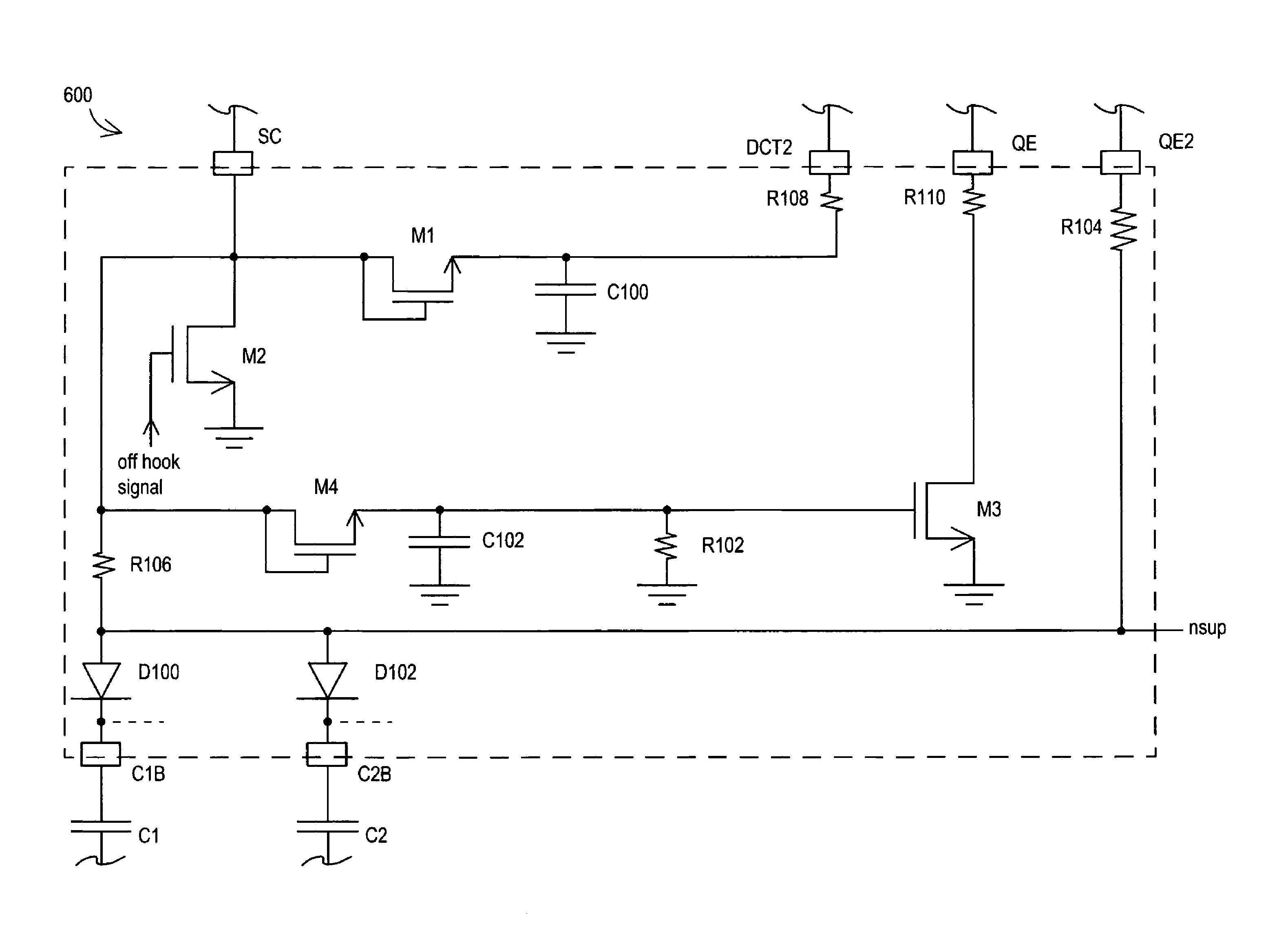
[0008]Disclosed herein is a surge clamp circuit that may be implemented with other parts of a DAA circuit to limit the total voltage developed across a line side capacitor due to charge pumping phenomenon occurring during longitudinal surge events (e.g., during a lightning strike or multiple high voltage longitudinal surges of other types that may be caused by telephone central office equipment failures, power equipment failures, etc.). As so employed, the disclosed surge clamp circuit may be employed to avoid build-up of damaging voltages and the resulting breakdown of surrounding components due to subsequent large current flows that may result due to charge pumping. Advantageously, the disclosed surge clamp circuit may make use of existing DAA hookswitch circuitry to clamp excessive voltages that result from charge pumping, without the expense and space requirements of conventional solutions to the charge pumping problem, e.g., varistor clamp devices.

Problems solved by technology

The components permitted for use across this isolation barrier are limited to transformers, high voltage capacitors, optoisolators, relays and large resistors.
However, it has been determined that in actual field usage, higher surge voltages (e.g. 3,000 to 5,000 volts) may occur across this isolation barrier.
When such voltages are present, air may begin to ionize anywhere within the enclosed system; dielectric breakdown may occur within the isolation barrier components, including high voltage capacitors.
In short, the damage to the system is undeterministic and may require the replacement of the entire system.
One of the most common causes of high voltage surges is a lightning strike, although telephone central office equipment and power equipment failures can also cause similar surges.
These surges cause tip and ring to rise, either positively or negatively, in voltage relative to earth.
High voltage surges may also occur as multiple surge events, often caused by multiple lightning strikes.
In this regard, a lightning strike can occur that has individual strokes with insufficient power to damage any components on a modem board.
If the lightning strike consists of multiple strokes, and if the multiple strokes are spaced close enough together such that charge placed on the capacitive node has insufficient time to dissipate, each stroke will result in energy being stored in the capacitor.
If the cumulative amount of energy stored produces a voltage across the capacitor that causes the capacitor to break down, then damage to some part of the modem circuit (either the capacitor itself or the components nearby) can occur.
This “pump-up” effect of capacitive nodes is challenging to reproduce in laboratory situations, but has been shown through laboratory simulations and experiments, as well as field study, to be a factor in DAA and modem damage.

Method used


Image

  • Surge clamp protection circuit
  • Surge clamp protection circuit
  • Surge clamp protection circuit

Examples


Embodiment Construction

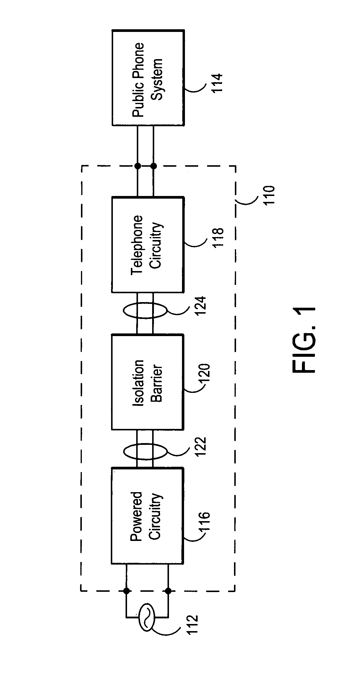
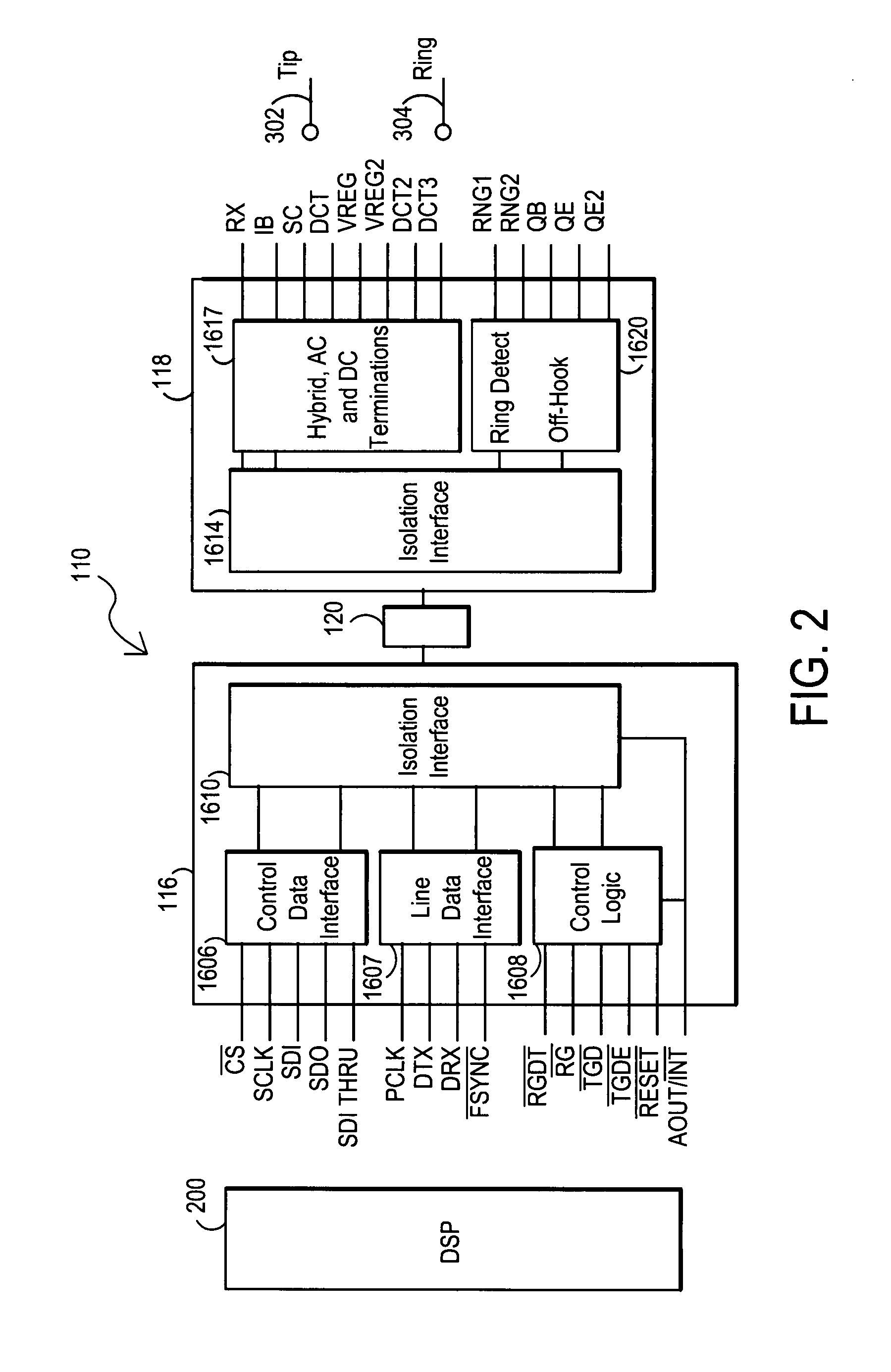
[0025]In order to provide a context for understanding this description, FIG. 1 illustrates a typical application for the present invention: circuitry that includes circuitry powered by a source external to the phone system. A basic telephone line side circuit 118 is connected to the public telephone system and does not have a separate power connection. DAA circuitry 110 for coupling to a phone line may be used with or incorporated within devices including, but not limited to, radio (cordless), modem, speakerphone, and answering machine devices that may require an external source of power 112, typically obtained by plugging the phone (or a power supply transformer / rectifier) into a typical 110-volt residential wall outlet. In order to protect public phone system 114 (and to comply with governmental regulations), it is necessary to isolate “powered circuitry”116 that is externally powered from “isolated circuitry”118 (isolated circuitry may also be called telephone line side circuit) ...


PUM


Abstract

A surge clamp circuit that may be implemented with DAA circuitry to limit the total voltage developed across one or more line side capacitors due to charge pumping phenomenon during a multi-transient events such as lightning strikes. The surge clamp circuit is capable of electronically sensing a transient event (e.g., lightning strike) and of momentarily turning on one or more components of a DAA hookswitch circuit during on hook mode to discharge the voltage developed across one or more line side capacitors before it reaches critical breakdown levels. The surge clamp circuit may be configured with a clamping sensitivity selected so that the DAA hookswitch circuitry is only activated or turned on upon occurrence of relatively large and potentially damaging transient events, and not upon occurrence of non-damaging transient events, such as operational signals.

Description

TECHNICAL FIELD OF THE INVENTION[0001]This invention relates to the field of isolation systems for use in selectively isolating electrical circuits from one another. More particularly, this invention relates to isolation systems used with digital access arrangement circuitry for connecting to telephone networks.BACKGROUND[0002]Electrical isolation barriers can be identified in many industrial, medical and communication applications where it is necessary to electrically isolate one section of electronic circuitry from another electronic section. In this context, isolation exists between two sections of electronic circuitry if a large magnitude voltage source (typically on the order of 1000 volts or more) connected between any two circuit nodes separated by the barrier causes less than a minimal amount of current flow (typically on the order of 10 milliamperes or less) through the voltage source. An electrical isolation barrier must exist, for example, in communication circuitry that ...

Claims


Application Information

Patent Timeline
IPC IPC(8): H04M1/00
CPCH04M1/745
Inventor DUPUIS, TIMOTHY J.THOMPSON, CHARLES D.
Owner SILICON LAB INC
Learn More