
Multi-channel circulator/isolator apparatus and method

a circulator/isolator and multi-channel technology, applied in the direction of electrical apparatus, waveguide devices, basic electric elements, etc., can solve the problems of difficult to meet the need for a stronger permanent magnet, space limitations imposed on phased array antennas, and the inability to incorporate any device into the already limited space available on most phased array antennas, etc., to achieve a high-configuration, compact configuration

Active Publication Date: 2007-08-14
THE BOEING CO
View PDF4 Cites 17 Cited by
  • Summary
  • Abstract
  • Description
  • Claims
  • Application Information

AI Technical Summary

Benefits of technology

The present invention is about a system and method for propagating electromagnetic waves in a multi-channel RF device. It uses a circulator with ferrite substrates and a magnet to form independent channels. The circulator can be incorporated into a compact configuration, making it suitable for applications where space limitations would normally prevent its use. The invention allows for efficient and reliable communication in a compact design.

Problems solved by technology

However, incorporating any device into the already limited space available on most phased array antennas can be an especially challenging task for the antenna designer.
The space limitations imposed in phased array antennas is due to the fact that the spacing of the radiating reception elements of the array is determined in part by the maximum scan angle that the antenna is required to achieve, and in part by the frequency at which the antenna is required to operate.
The need for a stronger permanent magnet is harder to meet due to material constraints.
Accordingly, the packaging of a conventional circulator / isolator becomes more and more difficult and challenging within phased array antennas as the operating frequency of the antenna increases or its performance requirements (i.e., scan angle requirement) increases.
These same packaging limitations are present in other forms of RF devices where there is simply insufficient space to accommodate a conventional circulator or isolator.

Method used


Image

  • Multi-channel circulator/isolator apparatus and method
  • Multi-channel circulator/isolator apparatus and method
  • Multi-channel circulator/isolator apparatus and method

Examples


Embodiment Construction

[0026]The following description of the preferred embodiment(s) is merely exemplary in nature and is in no way intended to limit the invention, its application, or uses.

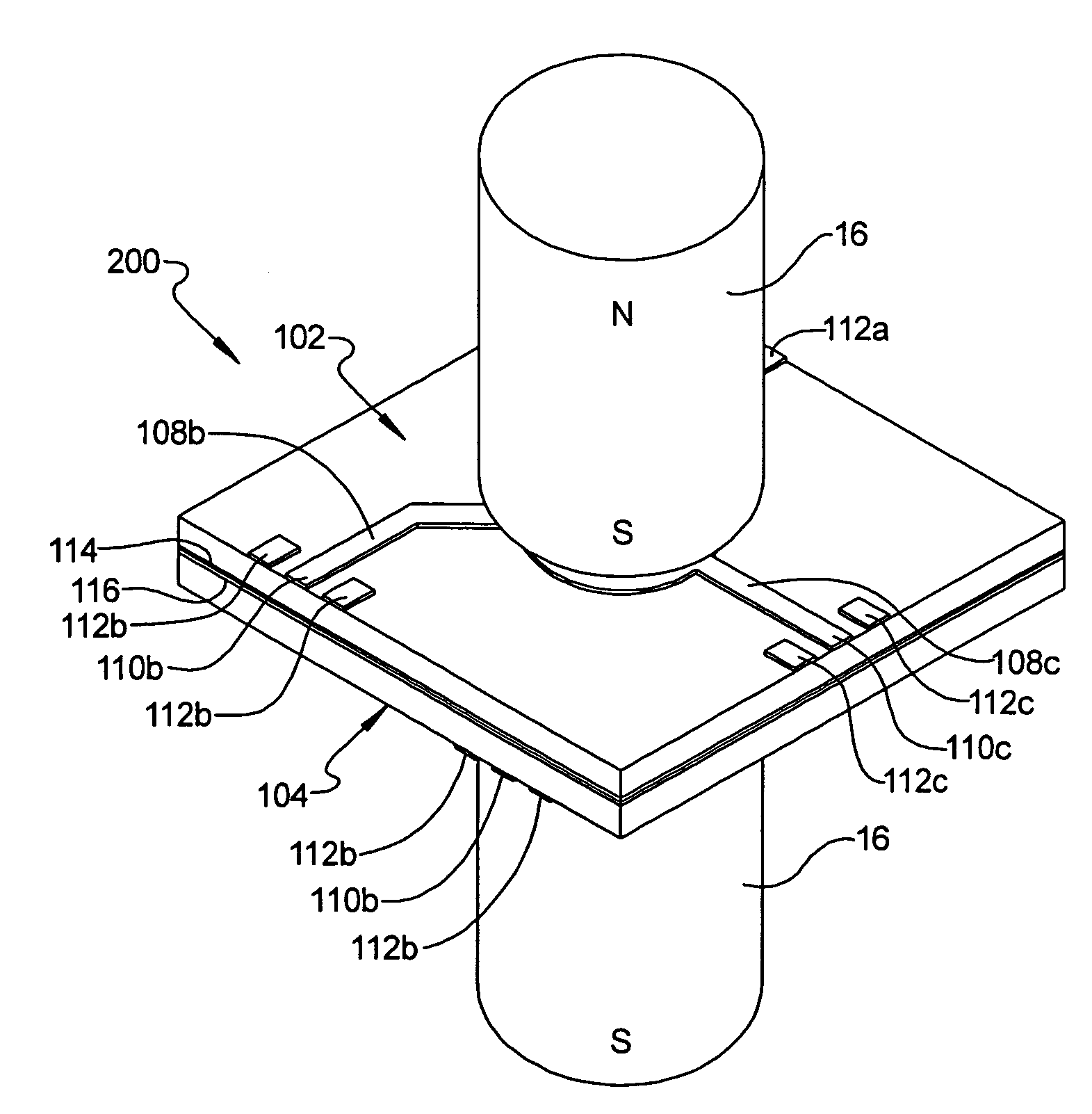
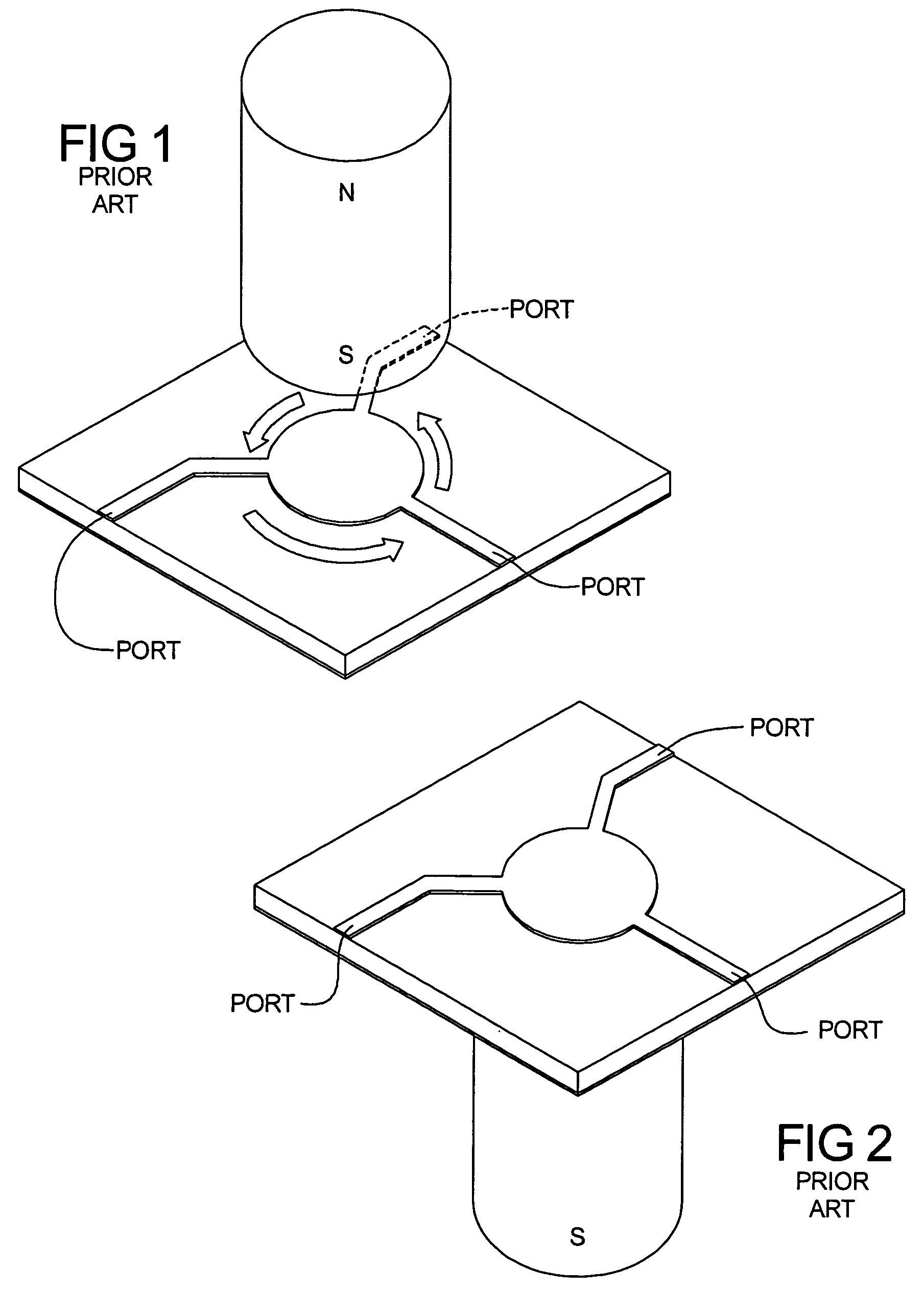
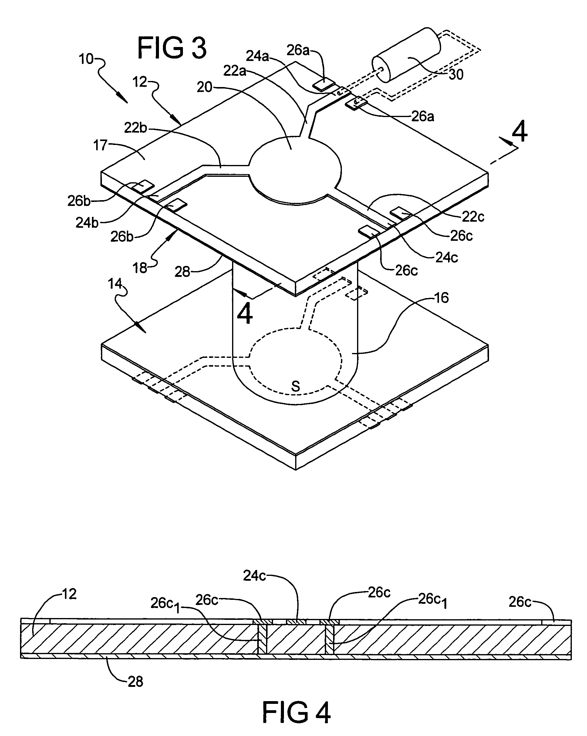
[0027]Referring to FIG. 3, a preferred embodiment of a multi-channel, non-reciprocal electromagnetic wave energy propagation apparatus is shown. The apparatus forms a circulator / isolator 10. The circulator / isolator 10 generally includes a first substrate 12 and a second substrate 14 positioned adjacent one another, and a permanent magnet 16 positioned between the substrates 12 and 14. In one preferred form the substrates 12 and 14 comprise yttrium iron garnet ferrite substrates that are formed in a planar configuration. Other suitable materials for the substrates 12 and 14 could be other types of ferrites such as Spinel or hexagonal, depending on the required operational frequency and other performance parameters. Ferrites are ideal for use in the preferred embodiments because they are ferromagnetic, are susceptible t...


PUM


Abstract

A multi-channel circulator or isolator well suited for use in phased array antennas or other RF devices where space and packaging constraints make the implementation of a conventional circular or isolator difficult or impossible. The multi-channel circulator / isolator can be configured as an isolator by the inclusion of one or more load resistors at one of its ports. In various configurations two or more ferrite substrates are provided that each provide a plurality of transmission ports. One or more permanent magnets are used to simultaneously provide the magnetic flux field through both of the substrates. The substrates can be configured such that they are spaced apart by a small distance, or positioned face to face in contact with one another. One or a plurality of magnets can be used depending upon RF requirements. Each substrate forms an independent electromagnetic wave propagation channel that limits the propagation of RF energy between its ports in one direction only.

Description

[0001]This invention was made with Government support under contract number NRO-000-02-C-0343 awarded by National Reconnaissance Office. The Government has certain rights in this invention.FIELD OF THE INVENTION[0002]The present invention relates to circulators and isolators used in RF devices, and more particularly to a multi-channel circulator or isolator having a packaging configuration especially well suited for use with phased array antenna systems and other RF devices where space and packaging limitations preclude the use of conventional circulators or isolators.BACKGROUND OF THE INVENTION[0003]In phased array antennas, radar systems and various other forms of electronic sensor and communications systems or subsystems, ferrite circulators and isolators provide important functions at RF front end circuits of such systems. Typically, such devices, which can be broadly termed “non-reciprocal electromagnetic energy propagation” devices, are used to restrict the flow of electromagn...

Claims


Application Information

Patent Timeline
Patent Type & Authority Patents(United States)
IPC IPC(8): H01P1/387
CPCH01P1/387
Inventor CHEN, MINGTAKEUCHI, JIMMY SPIETILA, DOUGLAS A
Owner THE BOEING CO
Learn More