
Detecting fire using cameras

a technology of fire detection and cameras, applied in the direction of fire alarms, fire alarm radiation actuation, instruments, etc., can solve the problems of high false alarm rate, questionable safe take-off prospect, etc., and achieve enhanced image signals.

Inactive Publication Date: 2007-08-14
SIMMONDS PRECISION PRODS
View PDF73 Cites 39 Cited by
  • Summary
  • Abstract
  • Description
  • Claims
  • Application Information

AI Technical Summary

Benefits of technology

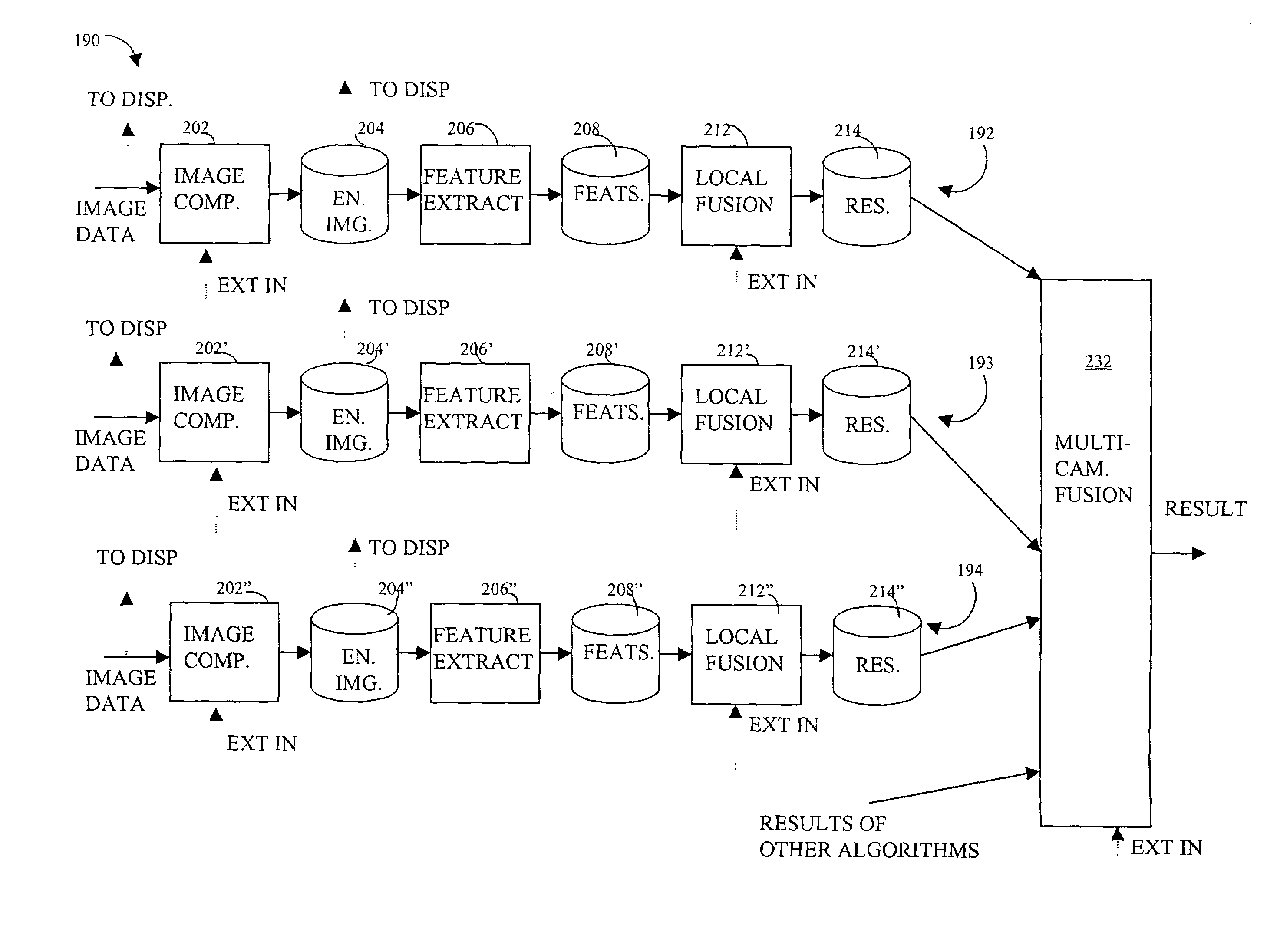
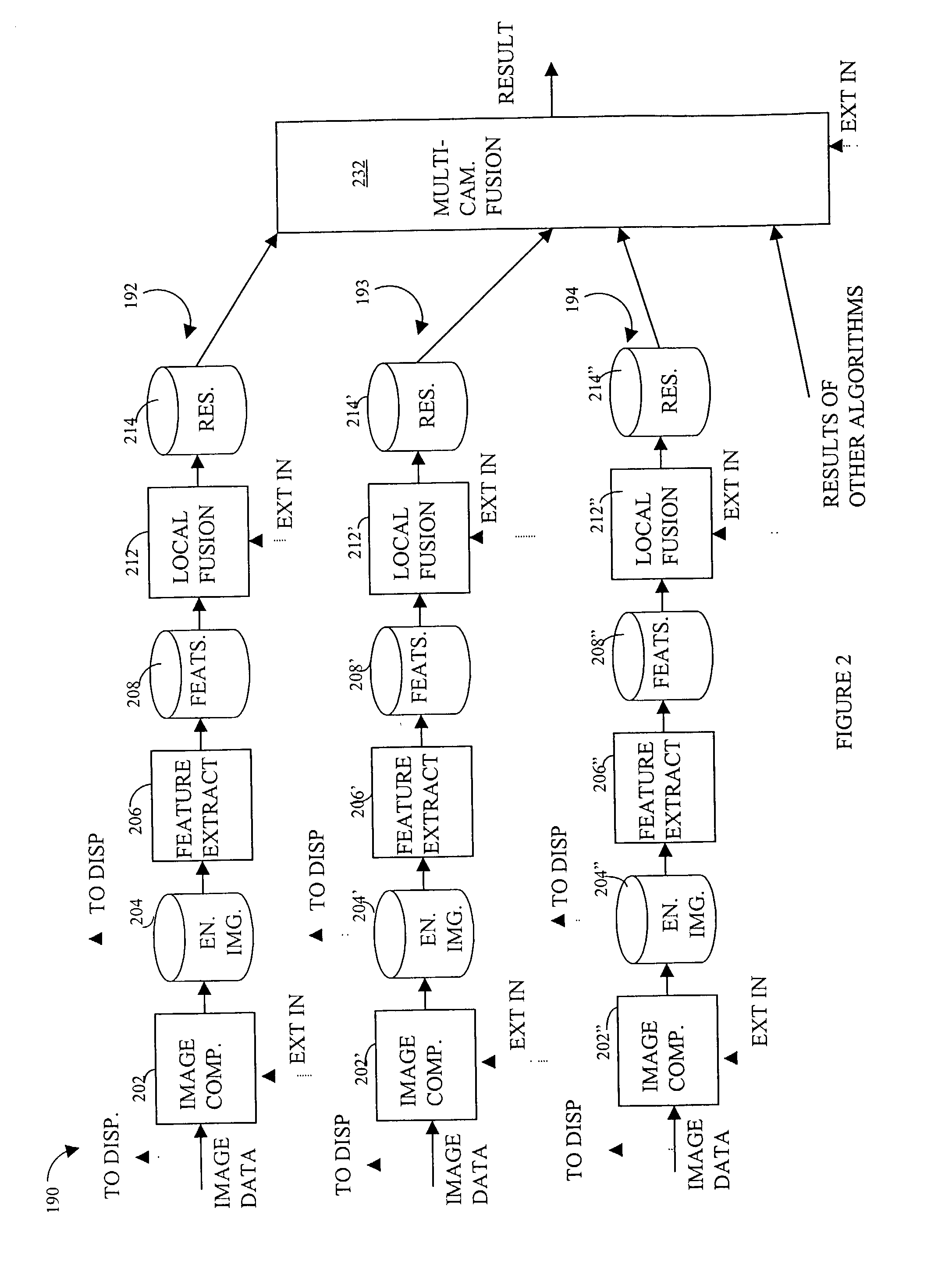
The present invention relates to a system for detecting fire in a video or image. The system uses a plurality of cameras to capture frames of video or images, which are then analyzed to detect the presence of fire. The system can detect fire by analyzing the energy indicators of each frame and comparing them to a reference frame. The system can also detect fire by analyzing the edge energy of each frame and comparing it to a reference edge energy corresponding to a non-fire condition. The system can also detect fire by analyzing the features of the frames, such as the energy indicators or edge energy, and combining them to detect fire. The system can be used in various applications, such as detecting fire in an aircraft cargo bay or detecting fire in a video or image.

Problems solved by technology

Conventional (mostly ionization-based) fire- and smoke-detection systems currently installed in aboard aircraft often suffer from high rates of false alarms.
In case of extended range operations of large jetliners over polar regions, a diversion after a false alarm may itself be dangerous, as the nearest airfield may be in a remote, sparsely populated location, may lack amenities necessary to accommodate 500+ passengers, and may render the prospect of safe take-off questionable.

Method used


Image

  • Detecting fire using cameras
  • Detecting fire using cameras
  • Detecting fire using cameras

Examples


Embodiment Construction

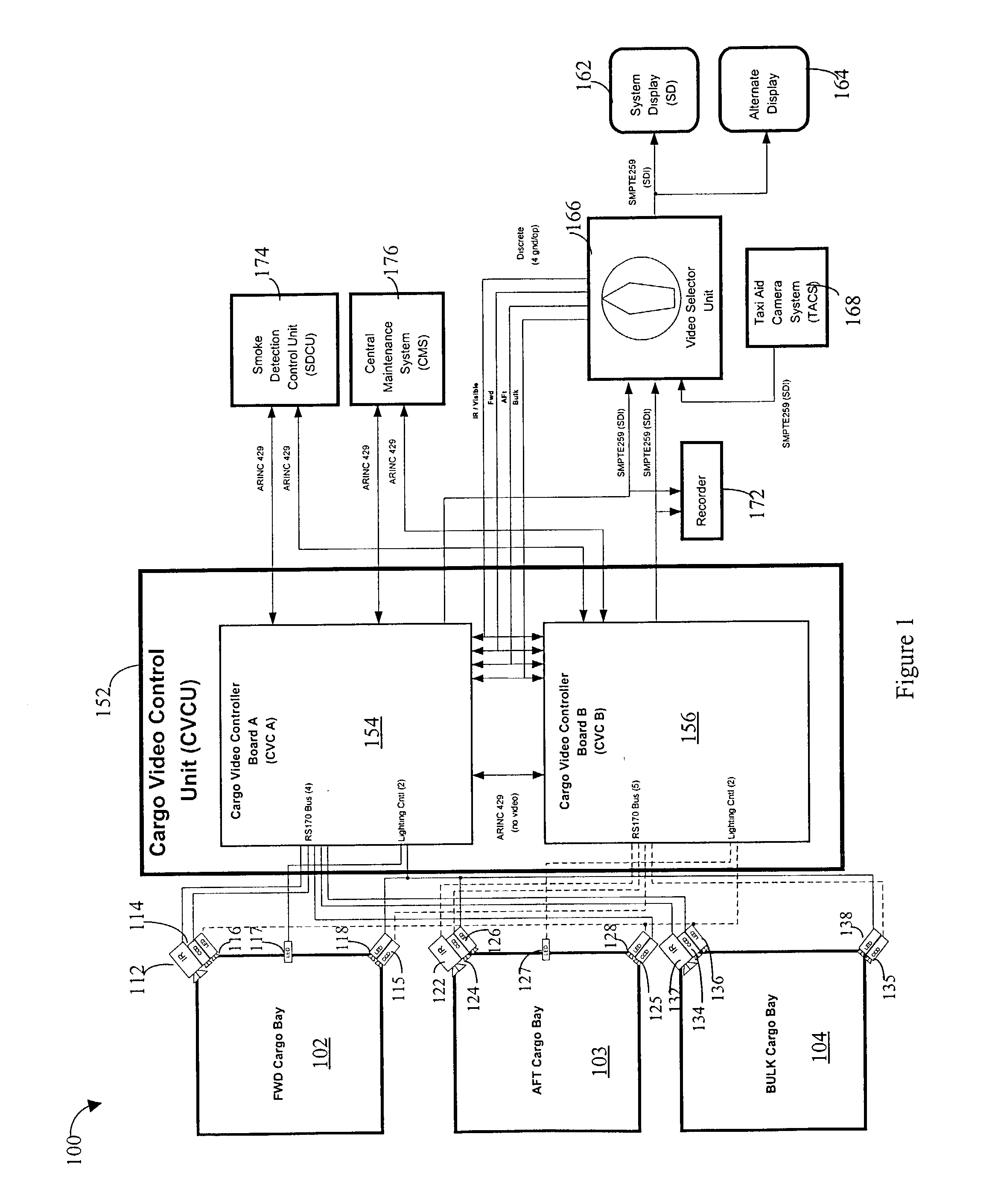
[0039]Referring to FIG. 1, a diagram 100 shows a system for monitoring and automatic detection and verification of fire within aircraft. The system described herein may be seen as a particular application of a more general Autonomous Vision System (AVS) which is a concept for a family of products. The AVS provides a user with a tireless automated surveillance capability to monitor various elements of the aircraft integrity. The system may be used in applications where surveillance is needed and simple decisions for immediate corrective actions are well defined. Most of the hardware and software described herein is expandable to various applications of the AVS where analysis of “visual” phenomena is expected.

[0040]The system monitors a plurality of aircraft cargo bays 102-104 to detect / verify the presence of fire. The cargo bay 102 includes an IR (infrared) camera 112, two CCD (charge coupled device) cameras 114, 115, and a plurality of LED (light emitting diodes) sources 116-118 tha...


PUM


Abstract

Detecting a fire, such as a fire in an aircraft cargo bay, includes receiving a plurality of frames of video information, determining an energy indicator for each of a subset of the plurality of frames, and detecting the presence of fire in response to the energy indicator for each of the subset of the plurality of frames corresponding to a predetermined pattern as a function of time. Detecting a fire may also include comparing energy indicators for each of the subset of the plurality of frames to a reference frame. The reference frame may correspond to a video frame taken when no fire is present or a video frame immediately preceding each of the subset of the plurality of frames. At least some of the subset of the plurality of frames may be provided by a camera having a sensitivity of between 400 nm and 1000 nm that may generates 640×480 pixels per frame. At least some of the subset of the plurality of frames may be provided by a CCD camera or a CMOS camera. At least some of the subset of the plurality of frames may be provided by a camera having a sensitivity of between 7 and 14 micrometers, which may be an IR camera.

Description

BACKGROUND OF THE INVENTION[0001]1. Technical Field[0002]This application relates to the field of automatic detection, isolation, verification and alarming, and more particularly to the field of detection, isolation, verification and alarming using video information.[0003]2. Description of Related Art[0004]Conventional (mostly ionization-based) fire- and smoke-detection systems currently installed in aboard aircraft often suffer from high rates of false alarms. Under current rules, once an alarm has been initiated (by the smoke detection system), the pilot is obligated to suppress the fire and divert the aircraft to the nearest emergency airfield. In case of extended range operations of large jetliners over polar regions, a diversion after a false alarm may itself be dangerous, as the nearest airfield may be in a remote, sparsely populated location, may lack amenities necessary to accommodate 500+ passengers, and may render the prospect of safe take-off questionable. Thus, it is des...

Claims


Application Information

Patent Timeline
Patent Type & Authority Patents(United States)
IPC IPC(8): H04N7/18G08B17/12
CPCG08B17/125
Inventor SADOK, MOKHTARZAKRZEWSKI, RADOSLAW ROMUALD
Owner SIMMONDS PRECISION PRODS
Learn More