Multiple axis accelerometer

a multi-axis accelerometer and accelerometer technology, applied in the field of accelerometers, can solve the problems of imposing a greater challenge on the electronics, causing packaging challenges, and requiring more complex electronics for capacitive sensors

Active Publication Date: 2007-08-21
INVENSENSE
View PDF8 Cites 166 Cited by
  • Summary
  • Abstract
  • Description
  • Claims
  • Application Information

AI Technical Summary

Problems solved by technology

However, the electronics for a capacitive sensor are typically more complex.
The movement to ever increasing miniaturization has imposed a greater challenge to the electronics.
This, however, poses some packaging challenges and consumes lateral space.
There are no known solutions to the problem of a 3 axis accelerometer compatible with a low cost multi-axes gyro.

Method used


Image

  • Multiple axis accelerometer
  • Multiple axis accelerometer
  • Multiple axis accelerometer

Examples


Embodiment Construction

[0027]The present invention relates generally to accelerometers and more specifically to multiple axis accelerometers. The following description is presented to enable one of ordinary skill in the art to make and use the invention and is provided in the context of a patent application and its requirements. Various modifications to the preferred embodiments and the generic principles and features described herein will be readily apparent to those skilled in the art. Thus, the present invention is not intended to be limited to the embodiments shown, but is to be accorded the widest scope consistent with the principles and features described herein.

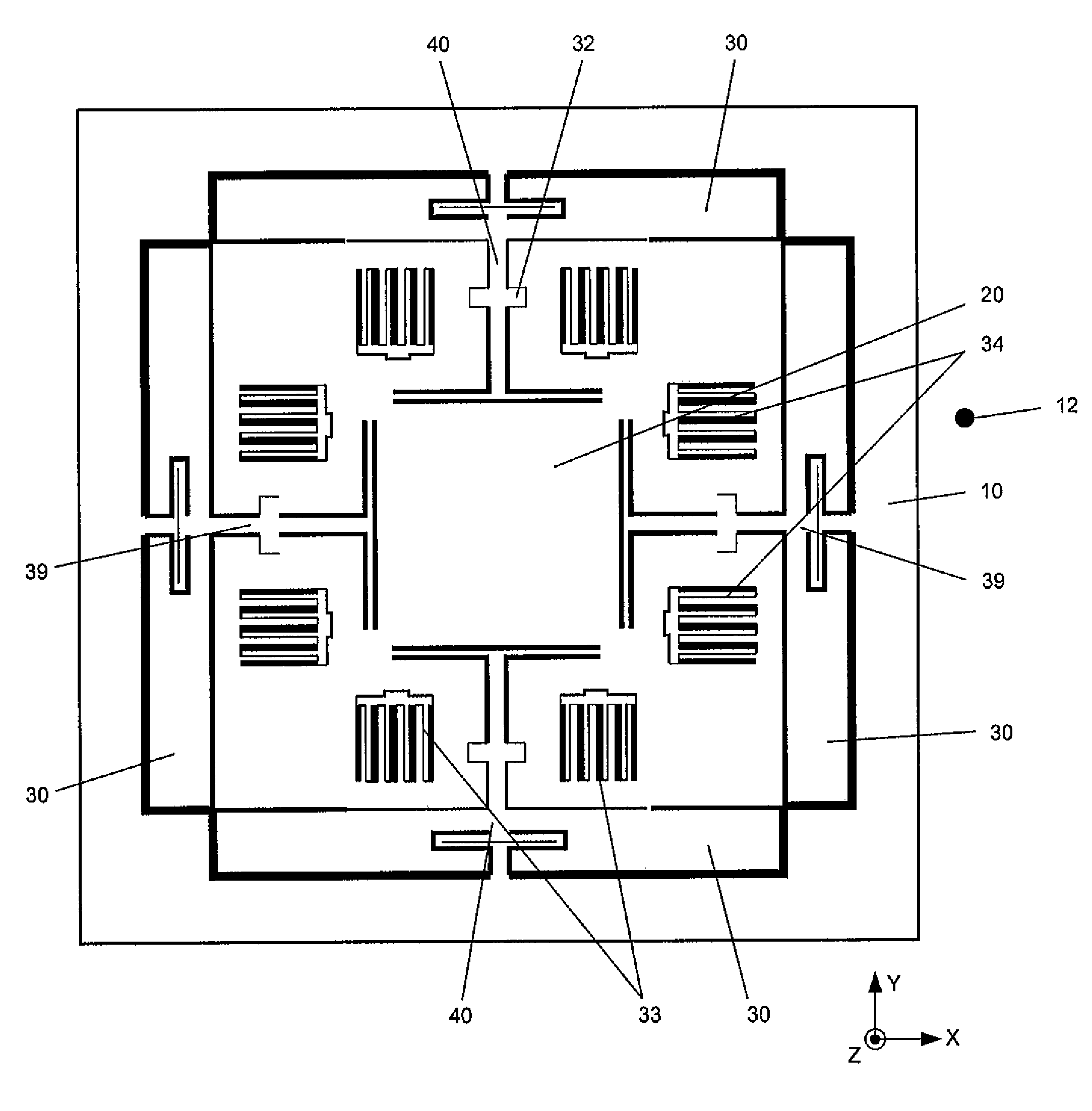
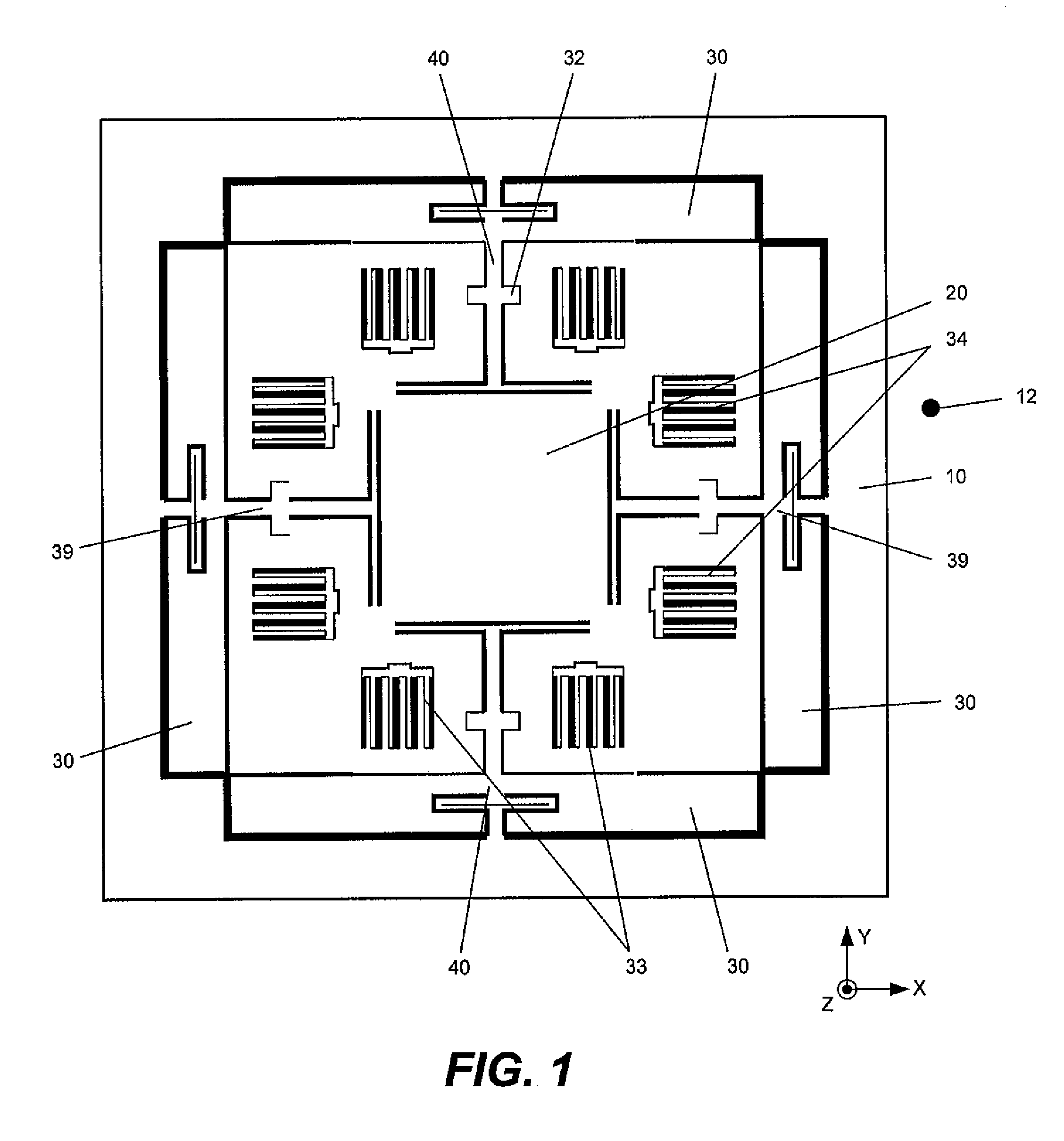
[0028]A method and system in accordance with the present invention provides for the integration of an electronics substrate with a second substrate containing the sensing proof mass. The proof mass is suspended in such a way as to be sensitive to acceleration forces in three mutually orthogonal directions namely X, Y, and Z, where Z is defin...


PUM


Abstract

A sensor for measuring acceleration in three mutually orthogonal axes, X, Y and Z is disclosed. The sensor comprises a sensor subassembly. The sensor subassembly further comprises a base which is substantially parallel to the X-Y sensing plane; a proof mass disposed in the X-Y sensing plane and constrained to move substantially in the X, Y, and Z, about by at least one linkage and is responsive to accelerations in the X, Y and Z directions. The sensor includes at least one paddle disposed in the sensing plane; and at least one pivot on the linkage. Finally, the sensor includes at least one electrode at the base plate and at least one transducer for each sensing direction of the sensor subassembly responsive to the acceleration.

Description

FIELD OF THE INVENTION[0001]The present invention relates generally to accelerometers and more specifically to multiple axis accelerometers.BACKGROUND OF THE INVENTION[0002]Many applications require the ability to sense acceleration and rate of rotation along three mutually orthogonal axes. In attempts to commercialize inertial measurement units for non-military applications, the cost and size of accelerometers have been addressed by various means. Sensing structures include capacitive devices as well as piezoresistive devices constructed using semiconductor manufacturing techniques. The capacitive devices are inherently less sensitive to temperature variations as they do not employ a resistance change which is highly sensitive to temperature. However, the electronics for a capacitive sensor are typically more complex.[0003]Capacitive devices generally include a proof mass which is mounted on a substrate. Electrodes are positioned in directions of interest to sense the deflection in...

Claims


Application Information

Patent Timeline
Patent Type & Authority Patents(United States)
IPC IPC(8): G01P15/125
CPCG01P1/023G01P15/0802G01P15/125G01P15/18G01P2015/082
Inventor NASIRI, STEVEN S.SEEGER, JOSEPH
Owner INVENSENSE
Why Eureka
Try Eureka