Bearing seal assembly for agricultural applications

a technology for agricultural applications and bearings, applied in the direction of bearing components, shafts and bearings, ball bearings, etc., can solve the problems of contaminants forcing into the bearing cavity, foreign materials typically not being flushed away, and maintenance-free bearings not being easy to lubrica

Active Publication Date: 2007-08-21
DEERE & COMPANY & PEER BEARING
View PDF16 Cites 28 Cited by
  • Summary
  • Abstract
  • Description
  • Claims
  • Application Information

AI Technical Summary

Benefits of technology

[0004]It is therefore an object of the present invention to provide an improved bearing assembly that overcomes most or all of the aforementioned problems. It is another object to provide such a system which eliminates most or all of the problems of contaminants entering the bearing during operation in harsh environmental conditions or during power washings.
[0005]It is another object of the present invention to provide an improved bearing assembly that has a reliable sealing system for resisting contamination in extreme environmental conditions. It is a further object to provide such an assembly that is particularly useful for operation in conditions wherein freezing, packing of material around the assembly or high pressure impact of material against the assembly is common. It is still another object to provide such a bearing assembly having significantly improved operating life compared to most previously available bearing when used in disk gangs or other agricultural implements.
[0006]In an embodiment of the invention, a bearing assembly includes a multi-lip seal with an extended shroud supported from an outer ring and projecting adjacent a stepped inner ring shoulder. A steel slinger supported from the inner ring is offset outwardly adjacent the shroud and includes a radially outer edge terminating closely adjacent the connection of the seal shroud to the outer ring. The slinger includes a outer portion angled inwardly from the radial direction and supporting a lip seal which contacts an angled portion of the seal shroud at a central location between the rings. A primary step machined on the inner ring prevents the slinger from being pushed into the seal. In one embodiment, a secondary step on the inner ring receives the innermost edge of the seal shroud and forms part of the labyrinth between the slinger and the seal shroud effectively sealing the bearing from contamination, even in the harshest of conditions.

Problems solved by technology

A bearing assembly for use in extreme conditions often encounters dirt and mud which in time can accumulate and pack against sealing structure and push contaminants into the bearing cavity.
Maintenance-free bearings cannot be easily lubricated, and therefore the foreign material typically cannot be flushed away.
In applications where power washers are used to clean areas around the bearing, contaminants are often forced into the bearing cavity by the cleaning process.
Once a bearing is contaminated, the bearing will eventually seize and fail to turn or become loose due to wear.
Contamination problems are particularly apparent in agricultural tillage implement bearings such as disk bearings operating in wet and muddy soil conditions.
Mud packing and pushing against the seals compromises the contaminant protection of the bearing seals.
Extreme temperature conditions and freezing of material around the bearing increases exposure to contamination.
Several times a year such bearings may be exposed to high pressure washing, further increasing the contamination problem.
Although bearing assemblies such as shown in U.S. Pat. No. 4,249,782 assigned to Deere & Company, have generally performed well most of the time, incidences of failure caused by the harsh environmental operating conditions still occur.

Method used


Image

  • Bearing seal assembly for agricultural applications
  • Bearing seal assembly for agricultural applications
  • Bearing seal assembly for agricultural applications

Examples


Embodiment Construction

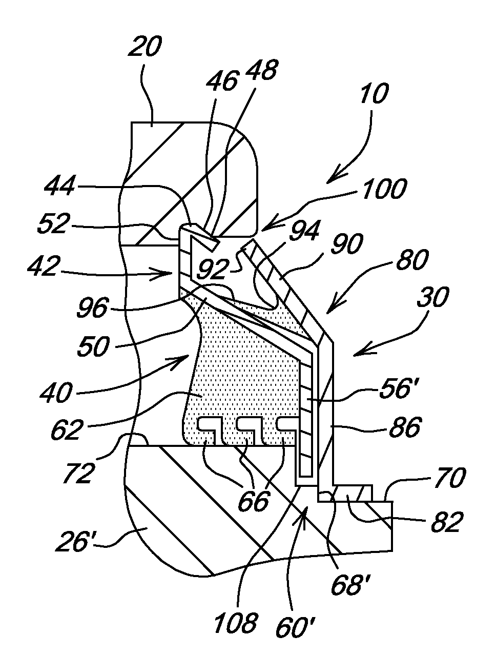
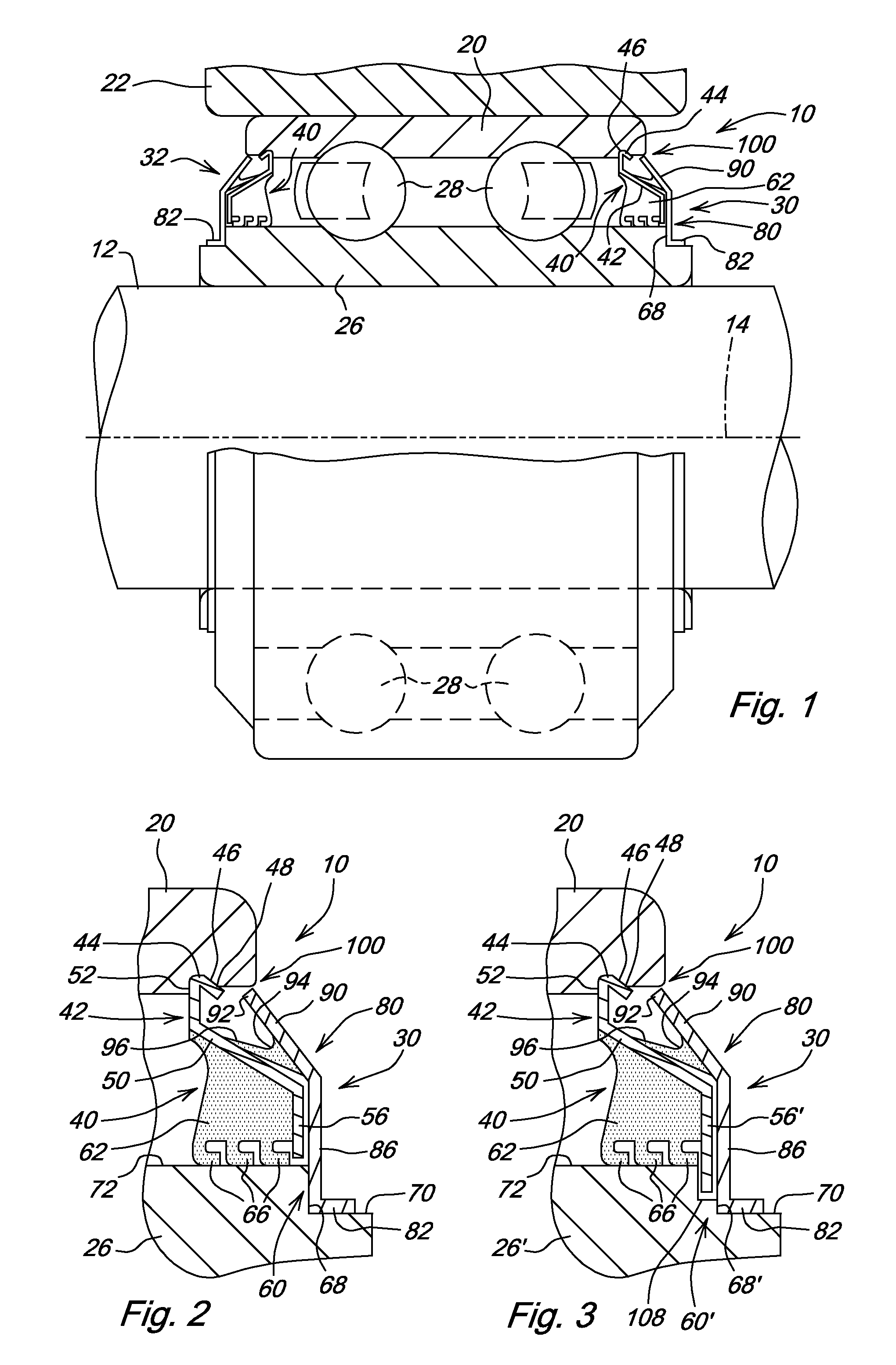
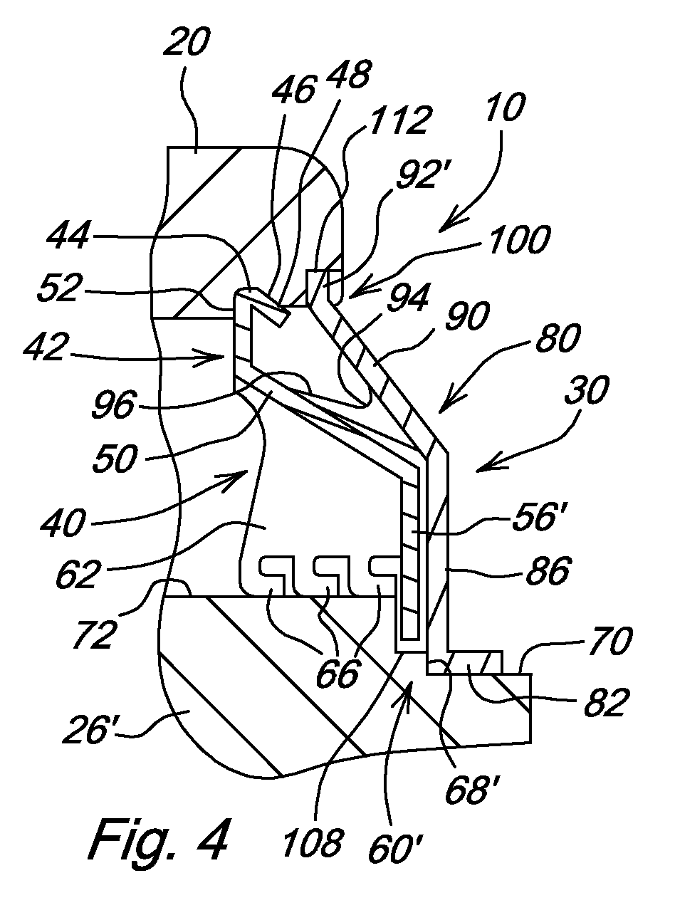
[0012]Referring to FIG. 1, therein is shown a bearing assembly 10 adapted for receiving a shaft 12 for rotation about an axis 14. The shaft 12 as shown is a disk gang axle supporting disk blades (not shown) for rotation in the soil.

[0013]The bearing assembly 10 includes an outer ring 20 non-rotatably supported in a disk standard 22 or other suitable mounting. An inner ring 26 is rotatably mounted by hardened steel balls or rollers 28. The shaft 12 is secured to the inner ring 26 for rotation about the axis 14. Although the bearing assembly is shown as a ball bearing, the seal structure described below may also be used with other types of bearings including roller bearings.

[0014]Sealing structure 30 and 32 is located at the axially outermost ends of the bearing assembly 10 to prevent contaminants from entering the assembly 10 and to resist external forces such as freezing material or dirt packed on the shaft that could otherwise compromise the blocking characteristics of the sealing ...


PUM


Abstract

A contaminant-resistant bearing assembly includes a multi-lip seal with an extended shroud supported from the outer ring and projecting adjacent a stepped inner ring shoulder. A steel slinger supported from the inner ring is offset outwardly adjacent the shroud and includes a radially outer edge terminating closely adjacent the connection of the seal shroud to the outer ring. The slinger includes an outer portion angled inwardly from the radial direction and supporting a lip seal which contacts an angled portion of the seal shroud at a central location between the rings. A primary step machined on the inner ring prevents the slinger from being pushed into the seal.

Description

FIELD OF THE INVENTION[0001]The present invention relates generally to a bearing assembly and, more specifically, to a contaminant resistant bearing assembly having lip seal, slinger and shroud structure particularly useful in harsh environmental conditions such as agricultural tillage applications.BACKGROUND OF THE INVENTION[0002]A bearing assembly for use in extreme conditions often encounters dirt and mud which in time can accumulate and pack against sealing structure and push contaminants into the bearing cavity. Maintenance-free bearings cannot be easily lubricated, and therefore the foreign material typically cannot be flushed away. In applications where power washers are used to clean areas around the bearing, contaminants are often forced into the bearing cavity by the cleaning process. Once a bearing is contaminated, the bearing will eventually seize and fail to turn or become loose due to wear.[0003]Contamination problems are particularly apparent in agricultural tillage i...

Claims


Application Information

Patent Timeline
Patent Type & Authority Patents(United States)
IPC IPC(8): F16C33/76
CPCF16C19/08F16C33/805F16C33/7859
Inventor GUTOWSKI, JORDAN ERICCOX, PHILIP DAVIDRUCKLE, JARROD RAYBIERL, JAMES FRANKLIN
Owner DEERE & COMPANY & PEER BEARING
Why Eureka
Try Eureka