Fuel cell

a fuel cell and connector technology, applied in the field of fuel cells, can solve the problems of increasing the workability of attaching work of the connector becomes worse, and the size of the fuel cell is totally larger

Active Publication Date: 2007-08-21
HONDA MOTOR CO LTD
View PDF10 Cites 2 Cited by
  • Summary
  • Abstract
  • Description
  • Claims
  • Application Information

AI Technical Summary

Benefits of technology

[0007]An exemplary object of the present invention, which is discovered to solve the above mentioned problems, is to provide a fuel cell having a connected structure which is high in reliability, easy to handle, and compact. Another exemplary object of the invention is to provide a fuel cell which can contribute to a workability of connecting connectors becoming favorable and the fuel cell becoming compact. Still another exemplary object of the invention is to provide a fuel cell, which can avoid breakages of terminals and / or connectors and poor connections of terminals with connectors and has a connected structure of terminals and connectors with good conductivity.
[0009]The fuel cell of the invention has unified the processing circuits processing cell voltage output signals (output levels) of the fuel cell stack and the connectors connecting the processing circuits with the terminals provided extending from the separators of the fuel cell, thereby having abolished connection points (in which the harnesses are attached / detached) of the processing circuits with the connectors. So, for connection, reliability can be improved and downsizing is possible. Moreover, with the casing enclosing the connectors and processing circuits, the fuel cell can be made compact and the processing circuits can be surely protected thanks to being shielded from surroundings and handling as a unit can be facilitated.
[0011]The above another fuel cell enables a workability of connecting connectors to be favorable because it suffices to connect a connector module, corresponding to each cluster of terminals in size, with the each cluster of terminals. Moreover, the connector modules are reversely provided in direction each other, thereby connector portions, which are formed as enclosing each terminal, being alternately provided at one side and the other side of the one end, so the connectors do not interfere with each other. In addition, main body portions do not also interfere with each other because they are formed narrower in width than the connector portions. Therefore, it is unnecessary to broaden a distance between separators in order to prevent the interference, thereby the fuel cell being able to be totally made compact. Moreover, the connector modules can be formed as a same shape, so parts can be made common, thereby cost being able to be lowered. Each terminal is provided at one end of each separator, so the connector module can be inserted from the one end only, thereby its access being able to be facilitated.
[0014]According to the fuel cell, if the separators are displaced in the stacked direction of the fuel cell, positions of the connectors and terminals do not be misaligned each other because they concurrently are displaced in the same direction. Accordingly, the fuel cell does not cause breakages of terminals and / or connectors and poor connections of terminals with connectors due to a separator displacement.

Problems solved by technology

Meantime, the more the number of separators becomes in a conventional voltage measurement, the more that of connectors to be inserted to each terminal, so there exists a problem that a workability of attaching work of these connectors becomes worse.
For the problem, although unifying a plurality of connectors is thought of to simplify the attaching work of these connectors, there exists another problem that a workability of attaching work of these connectors becomes worse in case of unifying a plurality of connectors due to a total weight increase of the module.
Moreover for the problem, although dividing the unified module into several modules and attaching them to one piece made of each cluster of terminals is thought of, it is necessary to broaden a distance between separators considering thickness of neighboring modules, thereby causing still another problem that a size of a fuel cell totally becomes larger.
Moreover, in the fuel cell with a module or modules described above, if separators are displaced along their stacked direction due to such as a separator thermal expansion deriving from an impact, vibration, and / or rapid temperature change, positions of modules attached as an outer covering and those of separators are relatively misaligned.
Such the position misalignment causes breakages of terminals and / or connectors and poor connections of terminals with connectors.
Furthermore, between the connectors connected with the terminals and circuit boards consisting of the processing circuit, a harness consisting of lead wires and the like connects, and a number of harnesses corresponding to that of cells or terminals are provided, thereby there existing a problem that a connected structure by the harnesses in itself is low in its reliability.
In addition, many lead wires are provided as the harnesses between the connectors and circuit boards, so there exists another problem that handling is not easy.

Method used


Image

  • Fuel cell
  • Fuel cell
  • Fuel cell

Examples


first embodiment

a. First Embodiment of the Invention

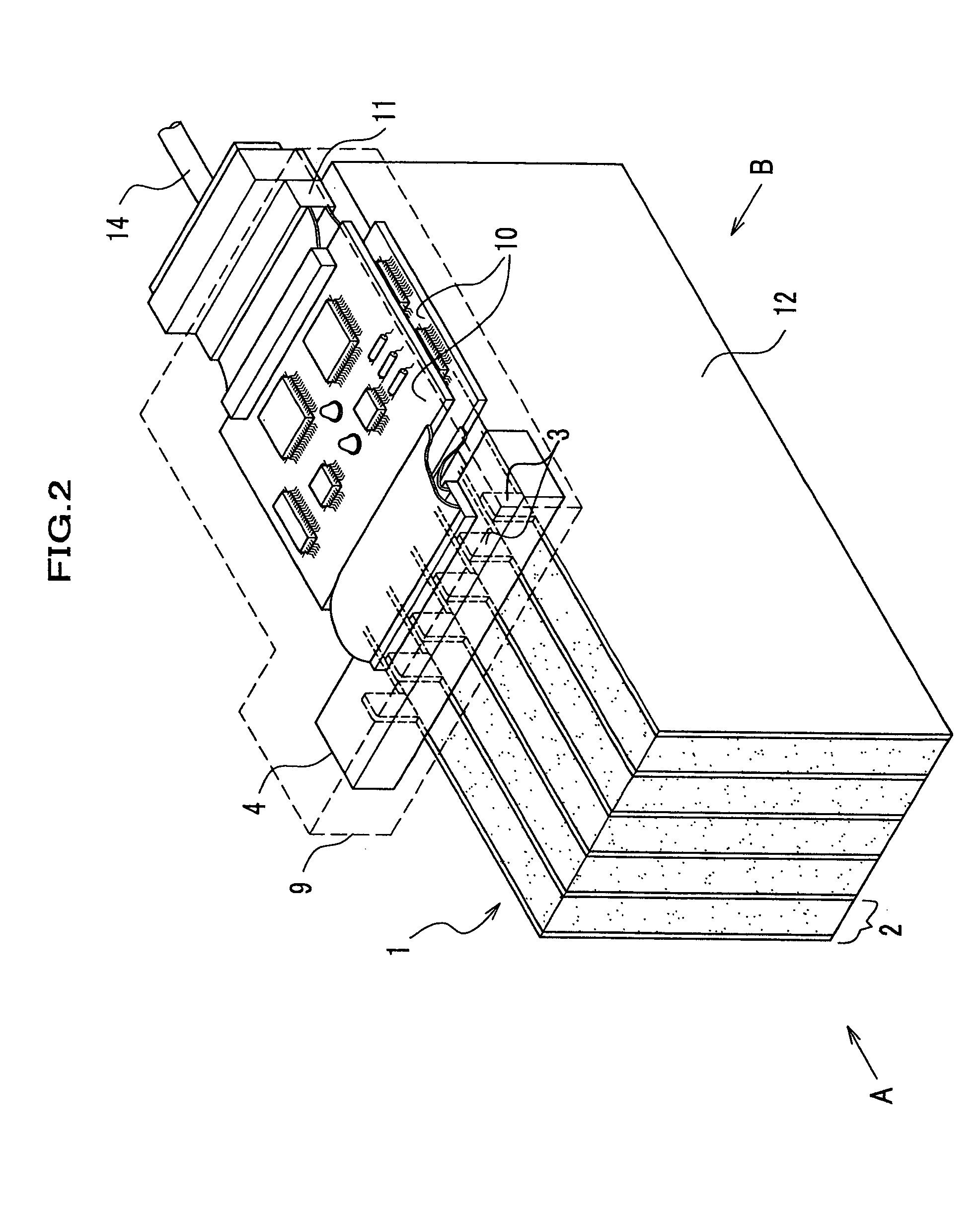
[0024]A first embodiment of a fuel cell related to the present invention is described referring to drawings. FIG. 2 is a perspective view schematically showing the fuel cell related to the first embodiment. As shown in FIG. 2, a fuel cell 1 is composed of a plurality of single cells 2 by stacking and is equipped with terminals 3 which are provided extending from separators 12 to lead voltages generated from the single cells 2. The terminals 3 are connected with a connector 4. The connector 4 is formed as one with circuit boards 10 consisting of a processing circuit which monitors / processes cell voltages (output levels) of the single cells 2. An electrical signal output from the circuit boards 10 are led to a control unit not shown in the drawing via a harness connector 11 and harness 14. Moreover, the connector 4 and circuit boards 10 are covered with a casing and formed as a compact box form, thereby being shielded and protected from surroundings...

second embodiment

b. Second Embodiment of the Invention

[0035]Then, a second embodiment of a fuel cell related to the present invention is described referring to drawings.

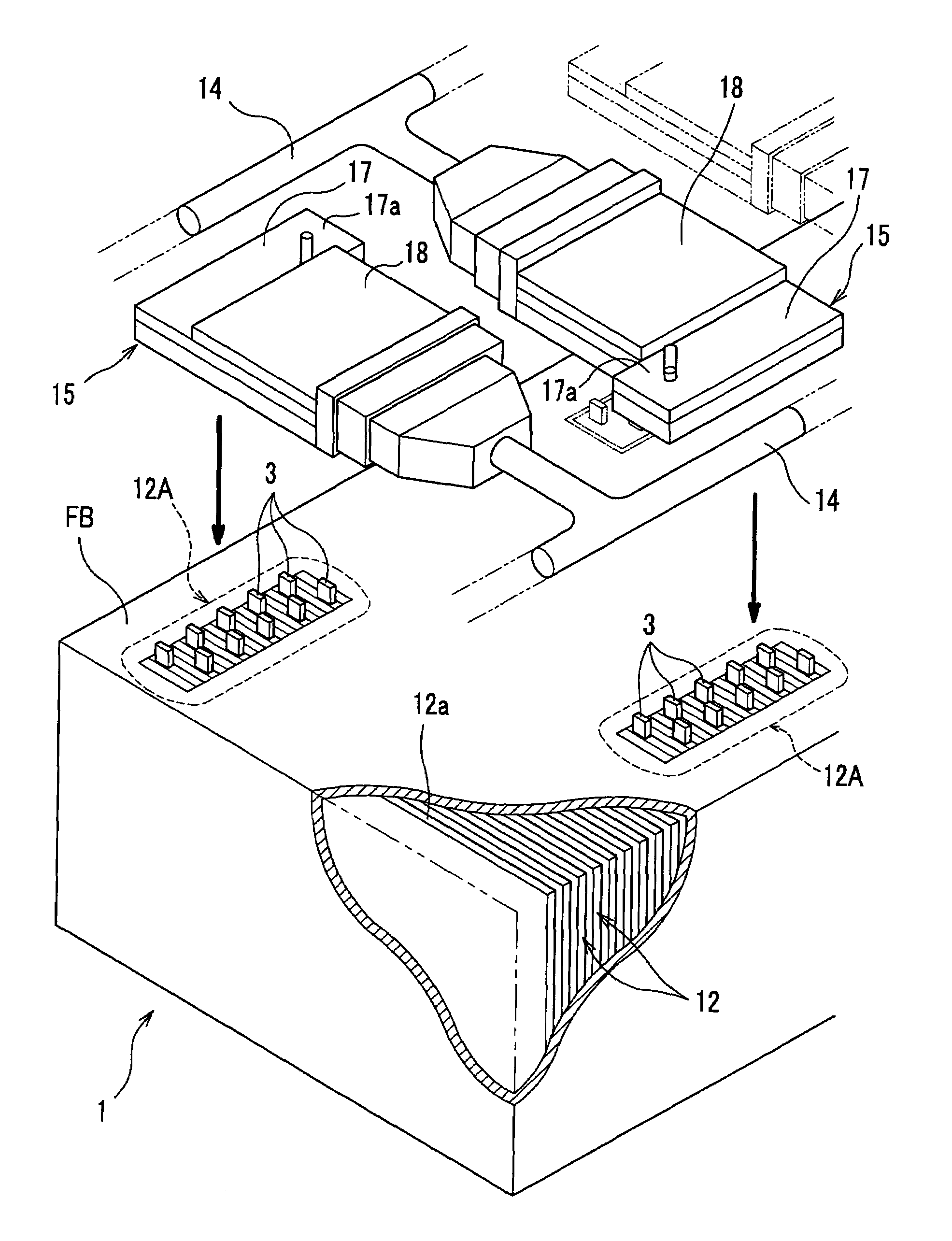
[0036]For referred drawings, FIG. 5 is a perspective view with a partial cutaway and shows the fuel cell related to the second embodiment. FIG. 6 is a plan view showing an arrangement of connector modules attached to the fuel cell of FIG. 2.

[0037]As shown in FIG. 5, the fuel cell 1 is composed so that membrane electrode assemblies not shown in the drawing are plurally stacked being pinched / held by the separators 12 and the assemblies are housed in a fuel box FB. Moreover, the fuel cell 1 is equipped with connector modules 15 to measure voltages between neighboring separators 12.

[0038]The terminals 3 which are extending upward (outside) are formed on an upper surface 12a (one end) of the separators 12. A plurality of terminals 3 formed in a plurality of separators 12 are separated into a plurality of terminal clusters 12A as a cluster...

third embodiment

c. Third Embodiment

[0052]Then, a third embodiment of a fuel cell related to the present invention is described referring to drawings.

[0053]For referred drawings, FIG. 7 is a perspective view with a partial cut away showing the fuel cell related to the invention. FIG. 8 is a partially enlarged perspective view around terminals. FIG. 9 is a partial section drawing of the fuel cell.

[0054]As shown in FIGS. 7 and 9, a fuel cell stack 19 is housed in the fuel cell box FB. The fuel cell stack 19 is equipped with a cell cluster 20 in which a plurality of the separators 12 pinching / holding the MEA and a movable separating plate 21 (stopper) described later is inserted between each cell cluster 20. On one side of the fuel cell stack 19, an end plate, disc spring 24, and backup plate 25 are arranged through an insulator 22 and on the other side without the disc spring, not shown in the drawings, an insulator, end plate, and backup plate are arranged in this order like the one side. Then, the b...


PUM

PropertyMeasurementUnit
electrical outputaaaaaaaaaa
voltagesaaaaaaaaaa
conductivityaaaaaaaaaa

Abstract

A fuel cell of the invention has unified a processing circuit processing a cell voltage output signal of a fuel cell stack and a connector connecting an circuit unit with terminals provided extending from separators of the fuel cell, thereby having abolished connection points (in which harnesses are attached and detached) of an electrical circuit unit with the connector. So, for connection, reliability can be improved, and downsizing is possible. Moreover, with a casing enclosing the connector and electrical circuit unit, the fuel cell can be made compact and the processing circuit can be surely protected thanks to being shielded from surroundings, thereby handling as a unit being able to be facilitated.

Description

FIELD OF THE INVENTION[0001]The present invention relates to a fuel cell, in particular, to a connected structure of terminals used for measuring voltages, connectors connected with the terminals, and circuit boards connected with the connectors.BACKGROUND OF THE INVENTION[0002]Conventionally, a fuel cell stack composed by stacking a plurality of so-called single cells which hold a membrane electrode assembly (hereinafter abbreviated as MEA) provided face to face with an anode electrode and cathode electrode interlaying a solid polymer electrolytic membrane by pinching / holding with separators made of metal or carbon with good conductivity is known. In a fuel cell in which the fuel cell stack is built in, a fuel cell gas supplied to the anode electrode is ionized on a catalyst electrode and moves to the cathode electrode through a moderately humidified solid polymer electrolytic membrane. Electrons generated during then are taken out into an external circuit and utilized as a direct ...

Claims


Application Information

Patent Timeline
Patent Type & Authority Patents(United States)
IPC IPC(8): H01M8/24H01M8/02H01M8/04H05K1/14
CPCH01M8/02H01M8/0247H01M8/04552H01M8/04873H01M8/241H01M8/2465H01M8/2475H05K1/144Y02E60/50
Inventor ARIYOSHI, TOSHIAKISATO, MASAHIKOTAKAHASHI, KENSATO, YUYAWACHI, DAISUKE
Owner HONDA MOTOR CO LTD
Why Eureka
Try Eureka