High density front access device

a front access device, high density technology, applied in the direction of coupling device connection, electrical apparatus construction details, support structure mounting, etc., can solve the problem of difficult access to the rear of the telecommunications rack

Inactive Publication Date: 2007-08-21
MICROSEMI CORP ANALOG MIXED SIGNAL GRP LTD
View PDF11 Cites 80 Cited by
  • Summary
  • Abstract
  • Description
  • Claims
  • Application Information

AI Technical Summary

Problems solved by technology

Connections in a telecommunication rack for which changes may need to be made during normal operations are typically supplied at the face of the modules, as access to the rear of the telecommunications rack is often difficult.
Unfortunately, the maximum number of RJ-45 jacks which can be placed in the front panel of a 1 U height module of a standard 19″ rack is no more than 56.

Method used


Image

  • High density front access device
  • High density front access device
  • High density front access device

Examples


first embodiment

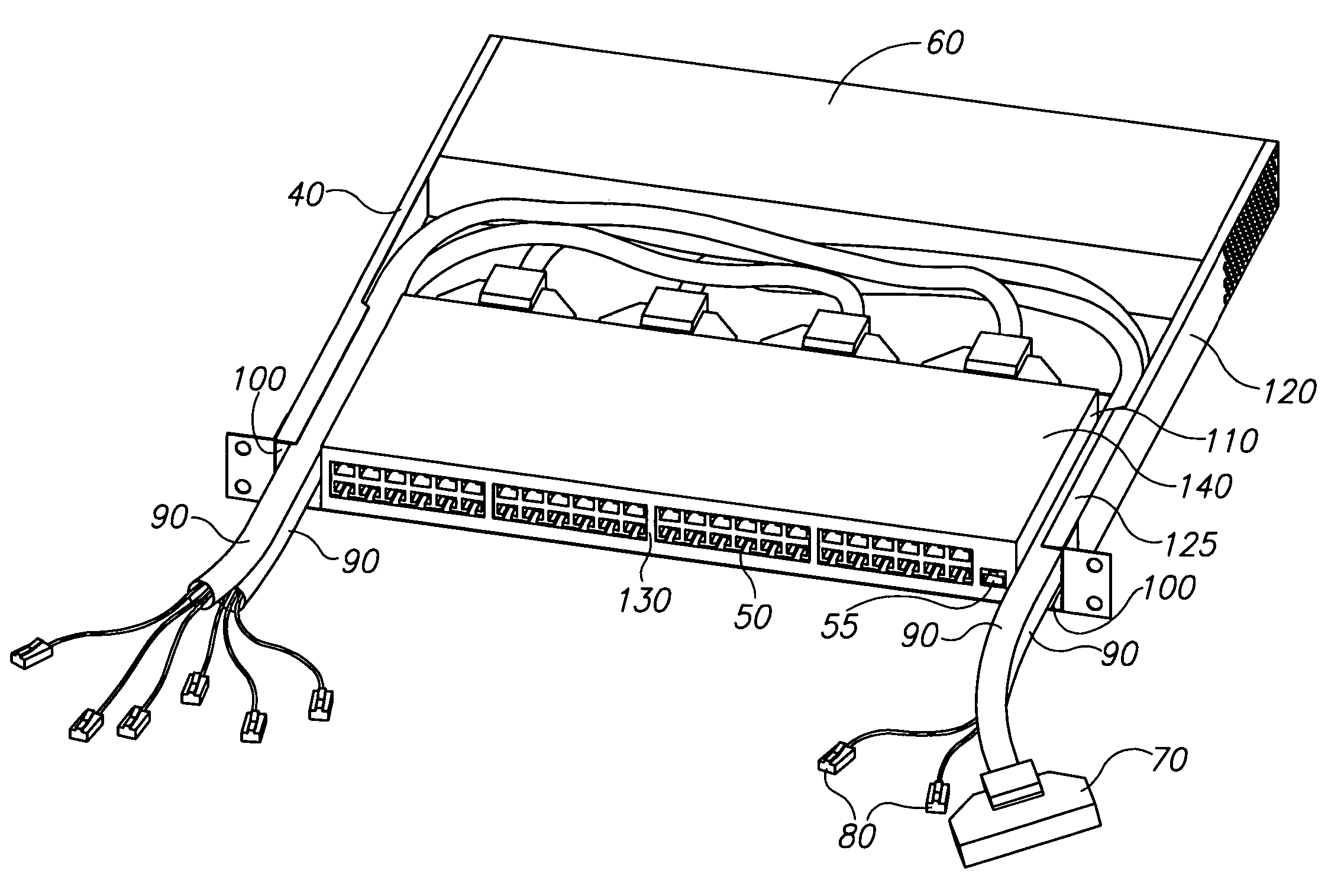
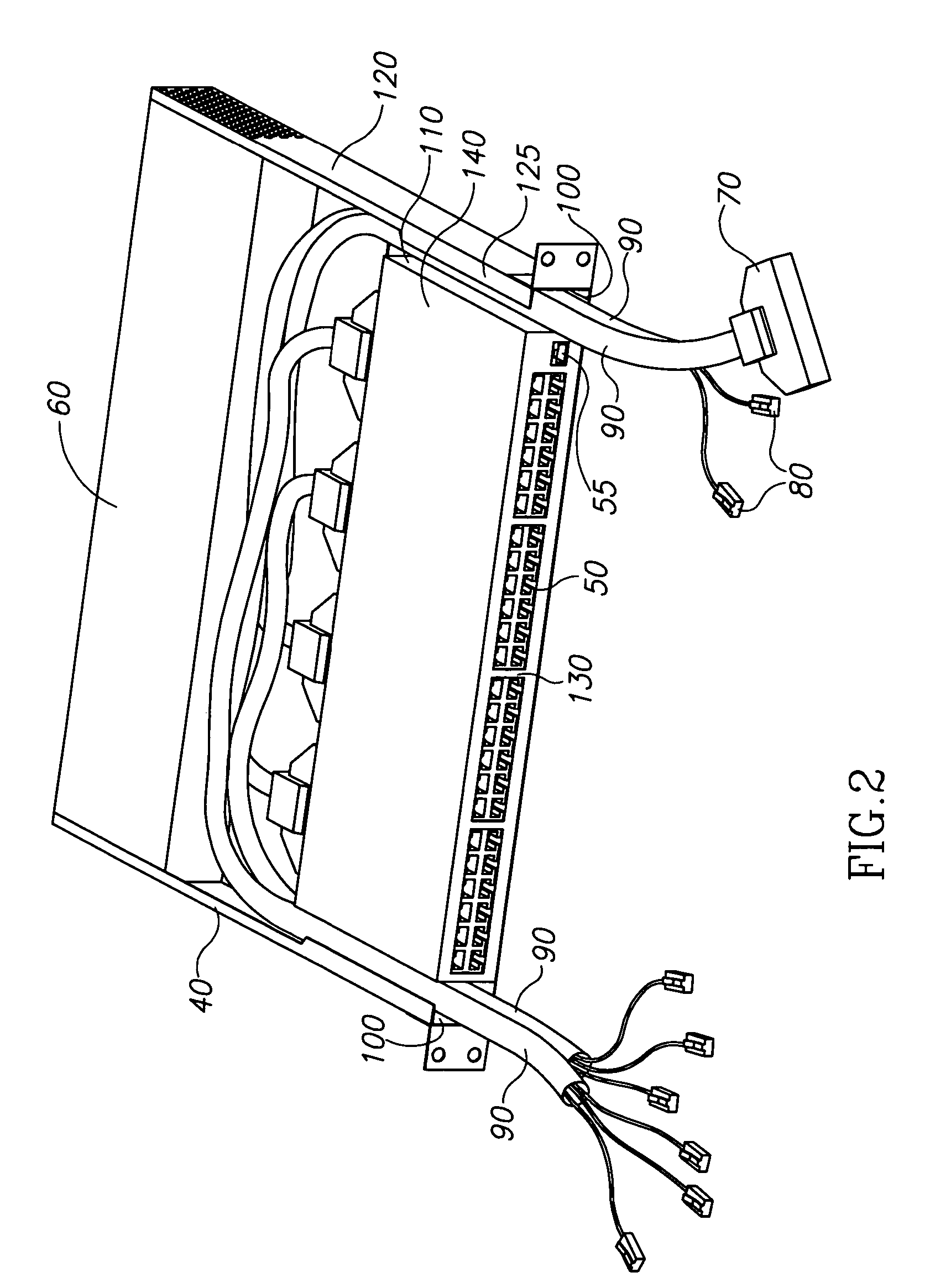
[0044]FIG. 4a is a high level perspective drawing depicting midspan equipment module 40 in accordance with the principle of the invention, comprising: chassis frame 120 exhibiting inner wall 240 and flange 125; Amp Champ connectors 70; sub-module chassis 140 having face 130, distal face 250, side wall 110, and network management jack 210; passageway 100; cables 90; power supply 60 exhibiting distal end 65; and power connection 220. Power supply 60 is situated at the rear of chassis frame 120 and is operatively connected to sub-module chassis 140 by power connection 220. Distal end 65 of power supply 60 is preferably coincident with, and forms the back face of, chassis frame 120. Cables 90 which terminate at one end in Amp Champ connectors 70 plugged into jacks located on distal face 250 of sub-module chassis 140 are passed through passageway 100 which is defined between an one inner wall 240 of chassis frame 120 and side wall 110 of sub-module chassis 140. A second end of each of ca...

second embodiment

[0047]FIG. 4b is a high level perspective drawing depicting midspan equipment module 40 in accordance with the principle of the invention, comprising: chassis frame 120 exhibiting inner wall 240 and flange 125; sub-module chassis 140 exhibiting face 130, distal face 250, RJ-45 connectors 50 and side wall 110; passageways 100; power supply 60 exhibiting distal end 65; power connection 220; opening 270; and cable tie down points 260. Power supply 60 is situated at the rear of midspan equipment module 40 and is operatively connected to sub-module chassis 140 by power connection 220. Distal end 65 is coincident with, and forms the back face of, chassis frame 120. For clarity cables have been omitted. RJ-45 connectors 50 located on distal face 250 of sub-module chassis 140 receive cables via passageway 100 defined between inner wall 240 of chassis frame 120 and side wall 110 of sub-module chassis 140. Opening 270 in the bottom wall of chassis frame 120 eases disconnection of RJ-45 plugs ...


PUM


Abstract

A high density device comprising: a chassis frame configured and dimensioned for mounting in a standardized telecommunications rack, the chassis frame defining a front plane and a back plane, the front plane being substantially coincident with a front support of the telecommunications rack; a sub-module chassis secured to the chassis frame, the sub-module chassis exhibiting a proximal face and a distal face; a first plurality of jacks located distal of the proximal face of the sub-module chassis; and a passageway formed between the sub-module chassis and an inner wall of the chassis frame, the passageway configured and dimensioned for the passage of cabling for connection to the first plurality of jacks.

Description

CROSS-REFERENCE TO RELATED APPLICATIONS[0001]This application claims priority from U.S. Provisional Patent Application Ser. No. 60 / 552,722 filed Mar. 15, 2004 entitled “High Density Front Access Device” the contents of which are incorporated herein by reference.BACKGROUND OF THE INVENTION[0002]The present invention relates to the field of rack mounted telecommunication devices, and in particular to a device having front access jacks distal of the device face.[0003]Electronic devices are often rack mounted, with a typical rack being 19″ wide. A device designed for a standardized size rack having standardized input and output plugs or jacks is often referred to as a module. The height of a module is often defined in terms of multiples of a unit height, with 1 unit height being 1.75″ or 44.45 mm.[0004]Midspan equipment in a local area network, such as an IEEE 802.3 compliant Ethernet network, supplies added functionality to the local area network. Midspan equipment is typically supplie...

Claims


Application Information

Patent Timeline
Patent Type & Authority Patents(United States)
IPC IPC(8): H05K5/00H01R29/00H01R12/50G06F1/16H04Q1/02H04Q1/14H05K7/14
CPCH04Q1/02H04Q1/09H05K7/1448H04Q1/021H04Q1/023H04Q2201/02H04Q2201/08H04Q2201/10
Inventor PINCU, DAVIDEPSTEIN, HAIM
Owner MICROSEMI CORP ANALOG MIXED SIGNAL GRP LTD
Why Eureka
Try Eureka