Lithographic apparatus and device manufacturing method

a technology of lithographic apparatus and manufacturing method, which is applied in the direction of photomechanical treatment, printing, instruments, etc., can solve the problems of reducing yield, compromising the quality of exposed patterns, and requiring several layers, so as to improve cdu and improve cdu for a given substrate. , the effect of improving cdu

Active Publication Date: 2007-08-21
ASML NETHERLANDS BV +1
View PDF27 Cites 5 Cited by
  • Summary
  • Abstract
  • Description
  • Claims
  • Application Information

AI Technical Summary

Benefits of technology

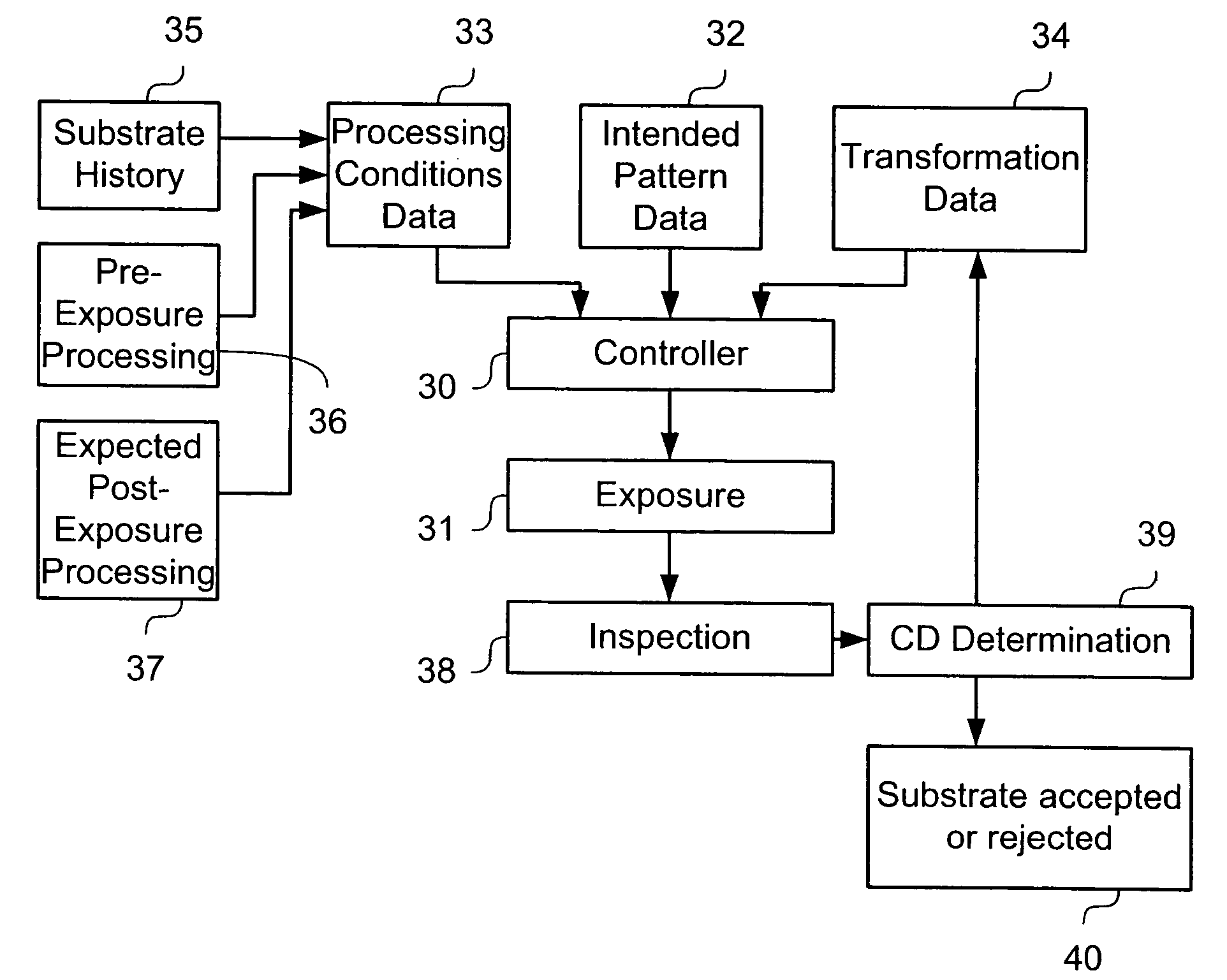
[0011]In one example, it is possible to compensate for variations that will be produced in a pattern formed on the substrate caused by the variations in pre-exposure and / or post-exposure processes. Therefore, a CDU for a given substrate can be improved.
[0012]In one example, the use of the lithographic apparatus allows a CDU to be improved not only across different regions of the substrate, but also from substrate to substrate.
[0013]In one example, the controller uses the processing conditions data to adjust, as required, a size of the pattern features that are generated in a pattern set on the array of individually controllable elements. For example, if the processing conditions data indicates that without correction the features formed on the substrate will be slightly oversized once processing of the substrate is complete, the controller adjusts the pattern set on the array of individually controllable elements to be slightly smaller than it would be were no correction made. Consequently, the pattern that is actually generated on the substrate is closer to the intended size, improving the CDU.
[0026]The first example is simpler to arrange and may be more accurate because it takes account of the interactions of processing conditions in different parts of the system. However, the second example requires less data to be stored and is more feasible if a large number of process parameters are to be taken account of.

Problems solved by technology

Furthermore, typically several layers are required.
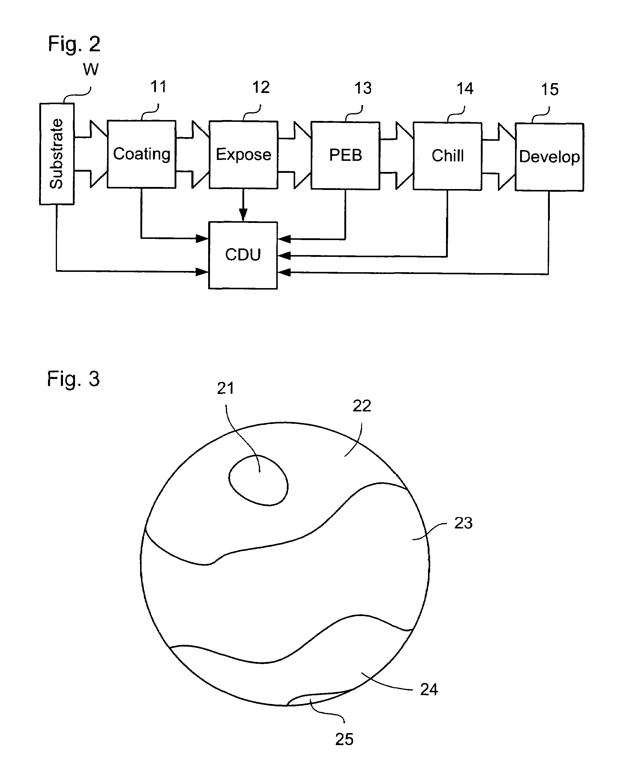
Therefore, variations in the pre-exposure and post-exposure conditions affect the size of features, and hence, the critical dimension uniformity (CDU), potentially compromising the quality of the exposed pattern.
If the CDU is not sufficient, a substrate may be rejected, reducing the yield.

Method used


Image

  • Lithographic apparatus and device manufacturing method
  • Lithographic apparatus and device manufacturing method
  • Lithographic apparatus and device manufacturing method

Examples


Embodiment Construction

Overview and Terminology

[0042]Although specific reference may be made in this text to the use of lithographic apparatus in the manufacture of integrated circuits (ICs), it should be understood that the lithographic apparatus described herein may have other applications, such as the manufacture of integrated optical systems, guidance and detection patterns for magnetic domain memories, flat panel displays, thin-film magnetic heads, etc. The skilled artisan will appreciate that, in the context of such alternative applications, any use of the terms “wafer” or “die” herein may be considered as synonymous with the more general terms “substrate” or “target portion,” respectively. The substrate referred to herein may be processed, before or after exposure, in for example a track (e.g., a tool that typically applies a layer of resist to a substrate and develops the exposed resist) or a metrology or inspection tool. Where applicable, the disclosure herein may be applied to such and other sub...


PUM


Abstract

A lithographic apparatus is provided that uses an array of individually controllable elements to pattern the beam of radiation. The critical dimension uniformity of a substrate patterned using the apparatus is improved by adjusting the pattern data provided to the array of individually controllable elements to compensate for process variation.

Description

BACKGROUND OF THE INVENTION[0001]1. Field of the Invention[0002]The present invention relates to a lithographic apparatus and a device manufacturing method.[0003]2. Related Art[0004]A lithographic apparatus is a machine that applies a desired pattern onto a target portion of a substrate. The lithographic apparatus can be used, for example, in the manufacture of integrated circuits (ICs), flat panel displays, and other devices involving fine structures. In a conventional lithographic apparatus, a patterning means, which is alternatively referred to as a mask or a reticle, may be used to generate a circuit pattern corresponding to an individual layer of the IC (or other device), and this pattern can be imaged onto a target portion (e.g., comprising part of one or several dies) on a substrate (e.g., a silicon wafer or glass plate) that has a layer of radiation-sensitive material (e.g., resist). Instead of a mask, the patterning means may comprise an array of individually controllable e...

Claims


Application Information

Patent Timeline
Patent Type & Authority Patents(United States)
IPC IPC(8): G03B27/32G03B27/54
CPCG03F7/70291G03F7/70525G03F7/2057G03F7/70275
Inventor BLEEKER, ARNO J.TEL, WIM T.
Owner ASML NETHERLANDS BV
Why Eureka
Try Eureka