Thermal management system for an aircraft

a technology of thermal management system and aircraft, applied in the direction of rocket engine plants, efficient propulsion technologies, machines/engines, etc., can solve the problems of system weight and aerodynamic drag, limited maximum operating temperature of aviation fuel, and progressive degradation of engine performance, etc., to achieve the effect of reducing the weight of air-to-liquid heat exchangers

Active Publication Date: 2007-08-28
RTX CORP
View PDF15 Cites 73 Cited by
  • Summary
  • Abstract
  • Description
  • Claims
  • Application Information

AI Technical Summary

Benefits of technology

[0009]The fuel based thermal management system according to the present invention includes a fuel stabilization system which permits the fuel to exceed the traditional coking temperatures. Air-to-liquid heat exchangers may be reduced and the heat generated by high temperature system components is rejected to the fuel which operates at a higher temperature due to the fuel stabilization system. High temperature components are arranged along the fuel flow path such that even at the higher operating temperatures the fuel operates as a heat sink to transfer heat from high temperature components to the fuel.
[0011]The present invention therefore provides an effective, lightweight thermal management system which minimizes air-to-liquid heat exchangers.

Problems solved by technology

Although effective, the maximum operating temperature of aviation fuel is limited by a coking temperature limit.
Coke deposits may result in a progressive degradation of engine performance.
A penalty paid for the use of ram air includes system weight and aerodynamic drag.
In addition, the installation of ram air circuits in an aircraft so as to convey the ram air to a point of use may be difficult.
Moreover, in the case of aircraft intended for military use, ram air inlets may provide an undesirable aircraft radar return.
A penalty paid for the use of bypass airflow for thermal management is the reduction in operating efficiency of the engine.
A penalty paid for the use of bleed air is a reduction in operating efficiency of the engine from which the air is bled.

Method used


Image

  • Thermal management system for an aircraft
  • Thermal management system for an aircraft

Examples


Embodiment Construction

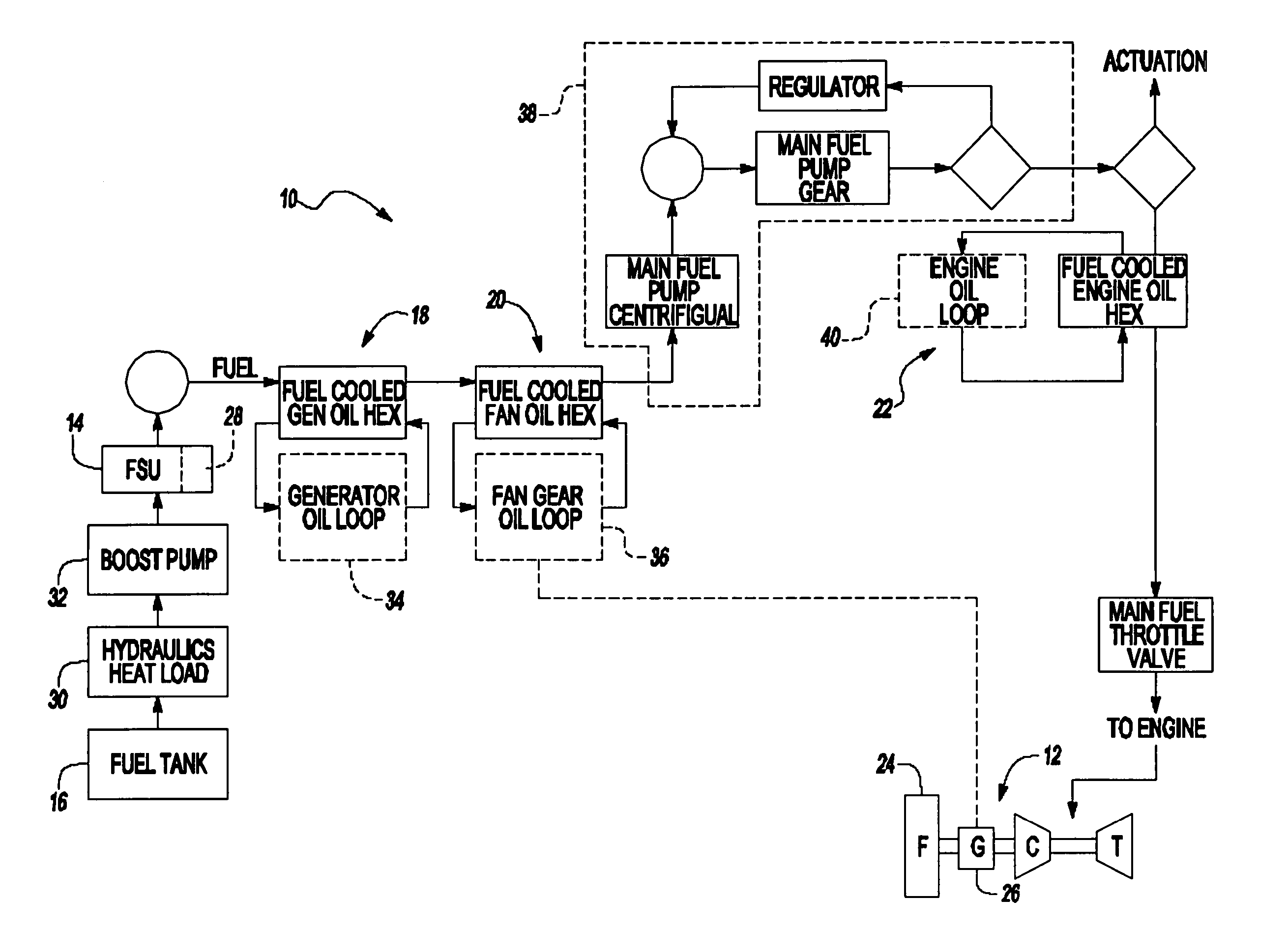
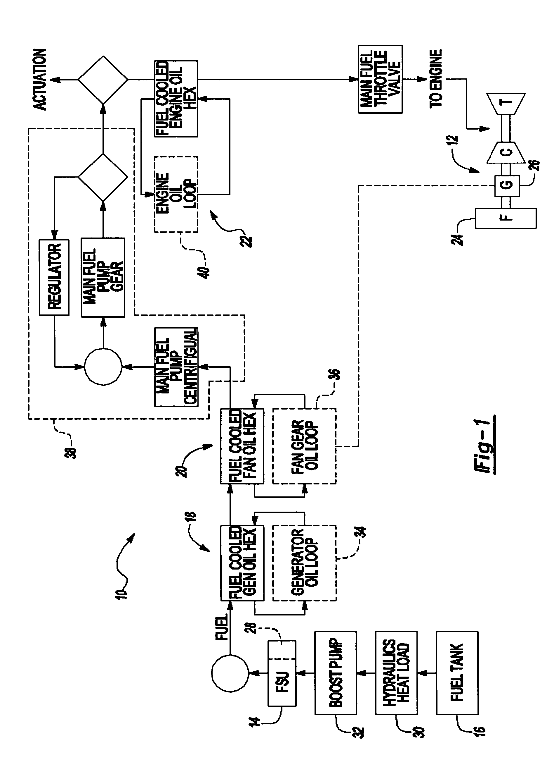
[0014]FIG. 1 illustrates a general perspective view of a fuel based thermal management system (TMS) 10 for an energy conversion device (ECD) 12. A fuel stabilization system (FSU) 14 receives a liquid fuel from a reservoir 16.

[0015]Typically, the fuel serves as a coolant for one or more (three shown) liquid-to-liquid heat exchanger sub-systems 18, 20, and 22. The fuel becomes progressively heated along the fuel flow path as the fuel draws thermal energy from components arranged along the fuel flow path. The heated fuel is then delivered to the fuel injectors for combustion within the ECD 12.

[0016]The ECD 12 may exist in a variety of forms in which the fuel, at some point prior to eventual use for processing, for combustion or for some form of energy release, acquires sufficient heat to support autoxidation reactions and coking if dissolved oxygen is present to any significant extent in the fuel. One form of the ECD 12 is a gas turbine engine, and particularly a geared turbofan engine...


PUM


Abstract

A fuel based thermal management system includes a fuel stabilization system which permits the fuel to exceed the traditional coking temperatures. High temperature components are arranged along the fuel flow path such that even at the higher operating temperatures the fuel operates as a heat sink to transfer heat from high temperature components to the fuel. An optimal high temperature ester-based oil permits an oil-loop to exceed current oil temperature limits and achieve a high temperature to permit efficient rejection of heat to the fuel late in the fuel flow path.

Description

BACKGROUND OF THE INVENTION[0001]The present invention relates to a thermal management system, and more particularly to a thermal management system which utilizes a fuel stabilization unit and isolates high temperature systems.[0002]Modem aircraft utilize sophisticated Thermal Management Systems (TMS) for thermal management and cooling. In typical modes of operation of the aircraft, lubricating oil, hydraulic fluid, and accessory drives require cooling. At the same time, the avionic systems of the aircraft will require cooling during operation, some by a liquid coolant and others by air. Concurrently, it is generally desirable to heat the fuel delivered to the main propulsion engines to maximize the efficiency of the engine.[0003]Typically, the fuel flow is utilized in combination with a fuel-oil heat exchanger. Although effective, the maximum operating temperature of aviation fuel is limited by a coking temperature limit. Coke deposits may result in a progressive degradation of eng...

Claims


Application Information

Patent Timeline
Patent Type & Authority Patents(United States)
IPC IPC(8): F02K9/64F02C7/22B64D37/00B64D37/32B64D37/34F02C7/06F02C7/236
CPCB64D37/34F02C7/22F02C7/236F05D2260/20Y02T50/675Y02T50/60B64D37/00B64D37/32
Inventor SABATINO, DANIELSPADACCINI, LOUIS J.KASLUSKY, SCOTT
Owner RTX CORP
Why Eureka
Try Eureka