Coupling structure of side member to cross member

a cross member and side member technology, applied in the direction of superstructure subunits, vehicle components, understructures, etc., can solve the problems of increasing the number of components, increasing the weight of the structure, and causing the structure to be complicated, so as to improve the assembly workability, increase rigidity, and strong fixation state

Inactive Publication Date: 2007-08-28
ISUZU MOTORS LTD
View PDF40 Cites 23 Cited by
  • Summary
  • Abstract
  • Description
  • Claims
  • Application Information

AI Technical Summary

Benefits of technology

[0015]In order to obtain the foregoing coupling structure, the gusset is fixed to the cross member in advance and the component is fixed to the side member by use of the attachment members. Thereafter, the gusset is fixed to the side member. In this event, the parts of the attachment members, which project from the inner surface of the vertical wall of the side member in the vehicle transverse direction, are housed in the recessed parts formed by the ribs. Thus, the vertical plate of the gusset comes into surface contact with the inner surface of the vertical wall of the side member in the vehicle transverse direction without interfering with the attachment members. Therefore, a strong fixation state is obtained between the gusset and the side member. Specifically, after the cross member and the gusset are assembled as one unit and the side member and the component are assembled as one unit, the both units can be assembled together. Thus, assembly workability is improved.
[0016]Moreover, the side member is coupled to the cross member by use of one gusset and the vertical plate of the gusset is reinforced by the ribs. Thus, without additionally requiring reinforcing members, it is possible to increase rigidity in a coupled portion of the side and cross members, particularly, torsional rigidity in a direction of rotation about the cross member.
[0017]In the coupling structure described above, second ribs may be provided in the gusset by providing a horizontal wall in the side member and fixing the component also to the horizontal wall by use of second attachment members. The horizontal wall extends inward in the vehicle transverse direction from one of upper and lower ends of the vertical wall and faces one of upper and lower horizontal plates of the gusset. The second attachment members penetrate the horizontal wall of the side member. The second ribs are formed in one of the horizontal plates of the gusset and protrude in an opposite direction to the horizontal wall of the side member. The second ribs form and define second recessed parts on a surface facing the horizontal wall. In a state where the gusset is fixed to the side member, interference between one of the horizontal plates of the gusset and parts of the second attachment members, which project toward the one of the horizontal plates from the horizontal wall of the side member, is avoided by the second recessed parts.
[0018]In the configuration described above, even if the component is also fixed to the horizontal wall of the side member by use of the second attachment members, interference between the second attachment members and the gusset is avoided by the second recessed parts defined by the second ribs. Specifically, the component such as the leaf spring bracket can be fixed to both of the vertical and horizontal walls of the side member without causing interference with the gusset. Thus, a stronger fixation state can be obtained.
[0019]Moreover, since one of the horizontal plates of the gusset is reinforced by the second ribs, it is possible to further increase the rigidity in the coupled portion of the side and cross members, particularly, the torsional rigidity in the direction of rotation about the cross member.
[0020]Furthermore, the second ribs in the horizontal plate may be formed continuously with the ribs on the vertical plate. Thus, compared to the case where the both ribs are formed to be separate from each other, a reinforcement effect thereof is significantly increased. Accordingly, rigidity of the gusset can be further improved.

Problems solved by technology

Thus, an assembly operation thereof is complicated.
Thus, an increase in the number of components, an increase in weight and a complication of the structure and the like may be induced.

Method used


Image

  • Coupling structure of side member to cross member
  • Coupling structure of side member to cross member
  • Coupling structure of side member to cross member

Examples


Embodiment Construction

[0029]With reference to the drawings, an embodiment of the present invention will be described below.

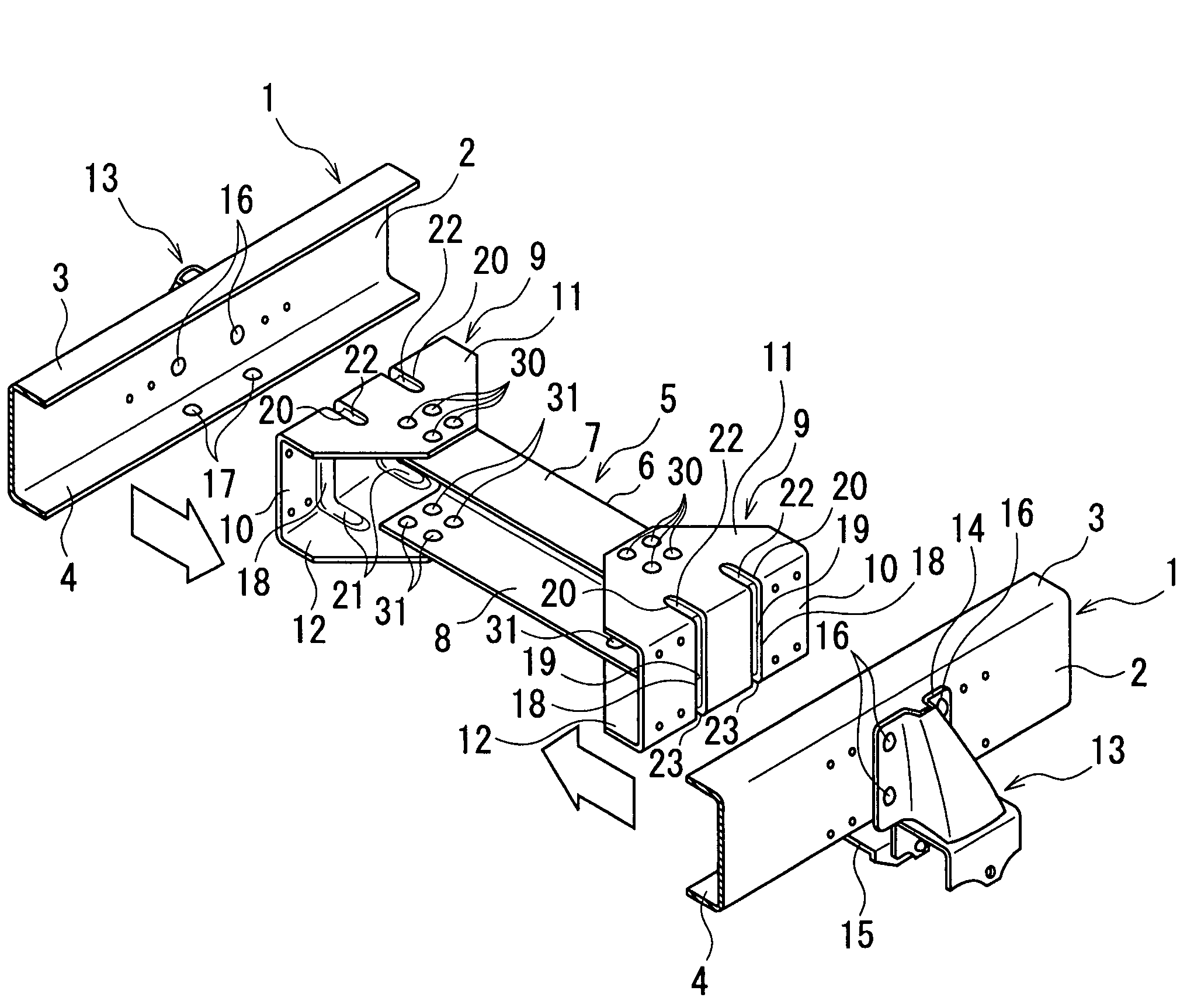
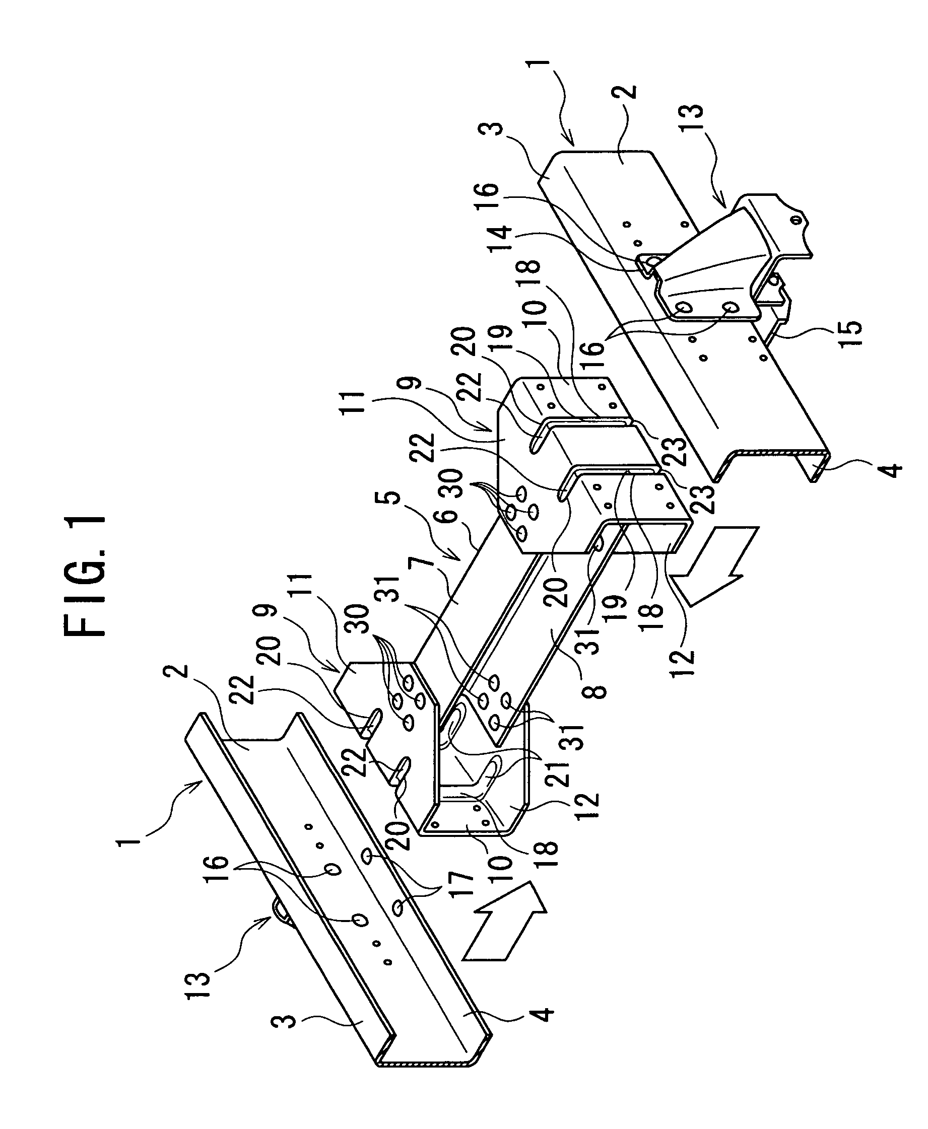
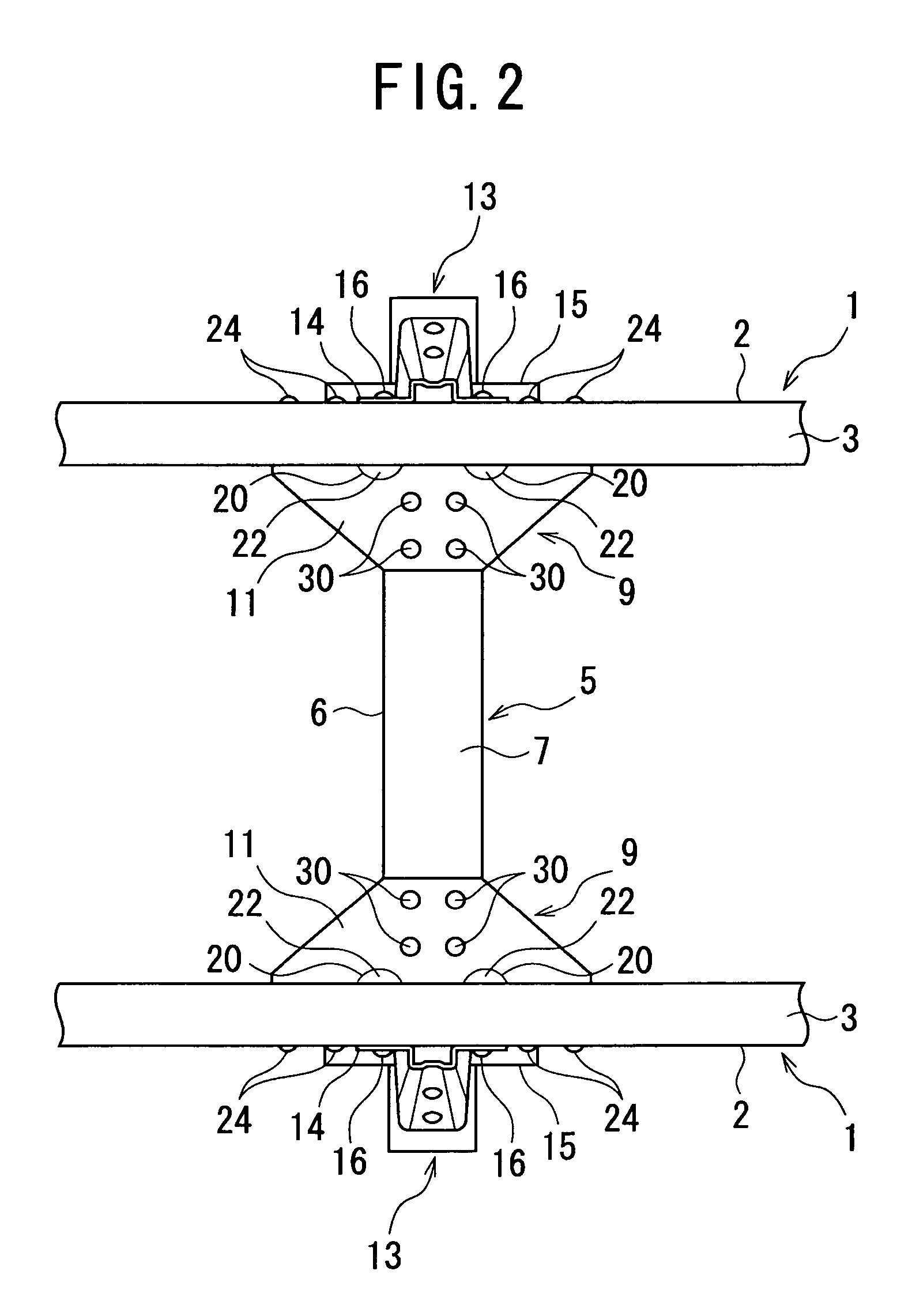
[0030]FIG. 1 is an exploded perspective view of a coupling structure according to this embodiment. FIG. 2 is a plan view showing an assembled state of FIG. 1. FIG. 3 is an enlarged view of a main part in which an upper horizontal plate of a side member shown in FIG. 2 is partially fractured. FIG. 4 is a cross-sectional view taken along the line IV-IV in FIG. 3. Note that, in the following description, a longitudinal direction is a longitudinal direction of a vehicle body and a left / right direction is a left / right direction in a state of facing the front of the vehicle body.

[0031]As shown in FIGS. 1 and 2, in a lower part of a vehicle body of an automobile with a chassis frame, a pair of left and right side members 1 and a cross member 5 as the chassis frame are provided. The side members 1 extend along the longitudinal direction of the vehicle body at both sides of a vehicle transver...


PUM


Abstract

A leaf spring bracket is fixed to an outer surface of a vertical wall of a side member in a vehicle transverse direction by use of rivets penetrating the vertical wall. A gusset which couples an end of a cross member in the vehicle transverse direction with the side member has a vertical plate and upper and lower horizontal plates. The vertical plate is fixed to the vertical wall of the side member. The upper and lower horizontal plates extend inward in the vehicle transverse direction from upper and lower ends of the vertical plate, respectively, and are fixed to upper and lower walls of the cross member, respectively. The vertical plate has ribs protruding inward in the vehicle transverse direction. The ribs form and define recessed parts in an outer surface of the vertical plate in the vehicle transverse direction. Parts of the rivets, which project from an inner surface of the vertical wall in the vehicle transverse direction, are housed in the recessed parts. Thus, the vertical plate is fixed in a state of coming into surface contact with the inner surface of the vertical wall in the vehicle transverse direction.

Description

[0001]This is a National Stage Application of International Application No. PCT / JP03 / 02473 filed Mar. 4, 2003.TECHNICAL FIELD[0002]The present invention relates to a coupling structure of side and cross members which form a chassis frame of a-vehicle body.BACKGROUND ART[0003]There has been heretofore known a structure for coupling a side member disposed in a longitudinal direction of a vehicle body to a cross member disposed in a transverse direction of a vehicle body by use of a gusset (as the prior art, see Japanese Utility Model Laid-Open Nos. H5 (1993)-58569 and H4 (1992)-51871).[0004]For example, as shown in FIGS. 5A and 5B, a side member 101 has an approximately U-shaped cross section including a vertical wall 102 and upper and lower horizontal walls 103 and 104. The upper and lower horizontal walls 103 and 104 are bent from upper and lower ends of the vertical wall 102, respectively, and extend inward in a vehicle transverse direction. A cross member 105 has an approximately ...

Claims


Application Information

Patent Timeline
Patent Type & Authority Patents(United States)
IPC IPC(8): B62D21/02B62D21/11B62D25/20
CPCB62D21/02
Inventor ITO, JUNMATSUMOTO, FUMITAKASAITO, MASANOBUSATO, HIROSHI
Owner ISUZU MOTORS LTD
Why Eureka
Try Eureka