Submersible pump drop pipe and casing assembly connection and method of manufacture

a technology of drop pipe and casing, which is applied in the direction of hose connection, screw threaded joint, mechanical apparatus, etc., can solve the problems of not being able to run the pipes into the well, unable to properly position the coupling, and unable to achieve the effect of drilling the pipe in the well

Inactive Publication Date: 2007-08-28
JOHNSON SCREENS
View PDF4 Cites 14 Cited by
  • Summary
  • Abstract
  • Description
  • Claims
  • Application Information

AI Technical Summary

Benefits of technology

[0018]In satisfaction of these and related objectives, Applicant's present invention provides a submersible pump drop pipe and casing assembly connection and method of manufacture. The drop pipe / casing has a seated connector and base. The seated connector has a first and second cylinder section, the first cylinder section being used to align and direct the base into the seated connector and to provide lateral strength to the pipe.

Problems solved by technology

The positioning of the couplings can take a great deal of effort to do properly.
In addition, pipe “dope” and cement have long curing times which makes what should be a relatively short job incredibly time consuming.
Unfortunately, with current practices and materials, well drillers do not have the ability to run the pipes into the well by simply and rapidly screwing one pipe into another.
Of interest is that maintenance of well pipes can often create more problems than may have existed simply due to the design of current pipes.
Existing pipe designs lack a significant degree of lateral strength such that if a section of pipe must be unscrewed and removed, the force needed to overcome the strength of the bonding agent can sheer the pipe and strip the threads.
In addition, it was found that laterally pushing on the pipe, a force of 1,000 pounds has to be exerted before the pipe will start leaking.

Method used


Image

  • Submersible pump drop pipe and casing assembly connection and method of manufacture
  • Submersible pump drop pipe and casing assembly connection and method of manufacture
  • Submersible pump drop pipe and casing assembly connection and method of manufacture

Examples


Embodiment Construction

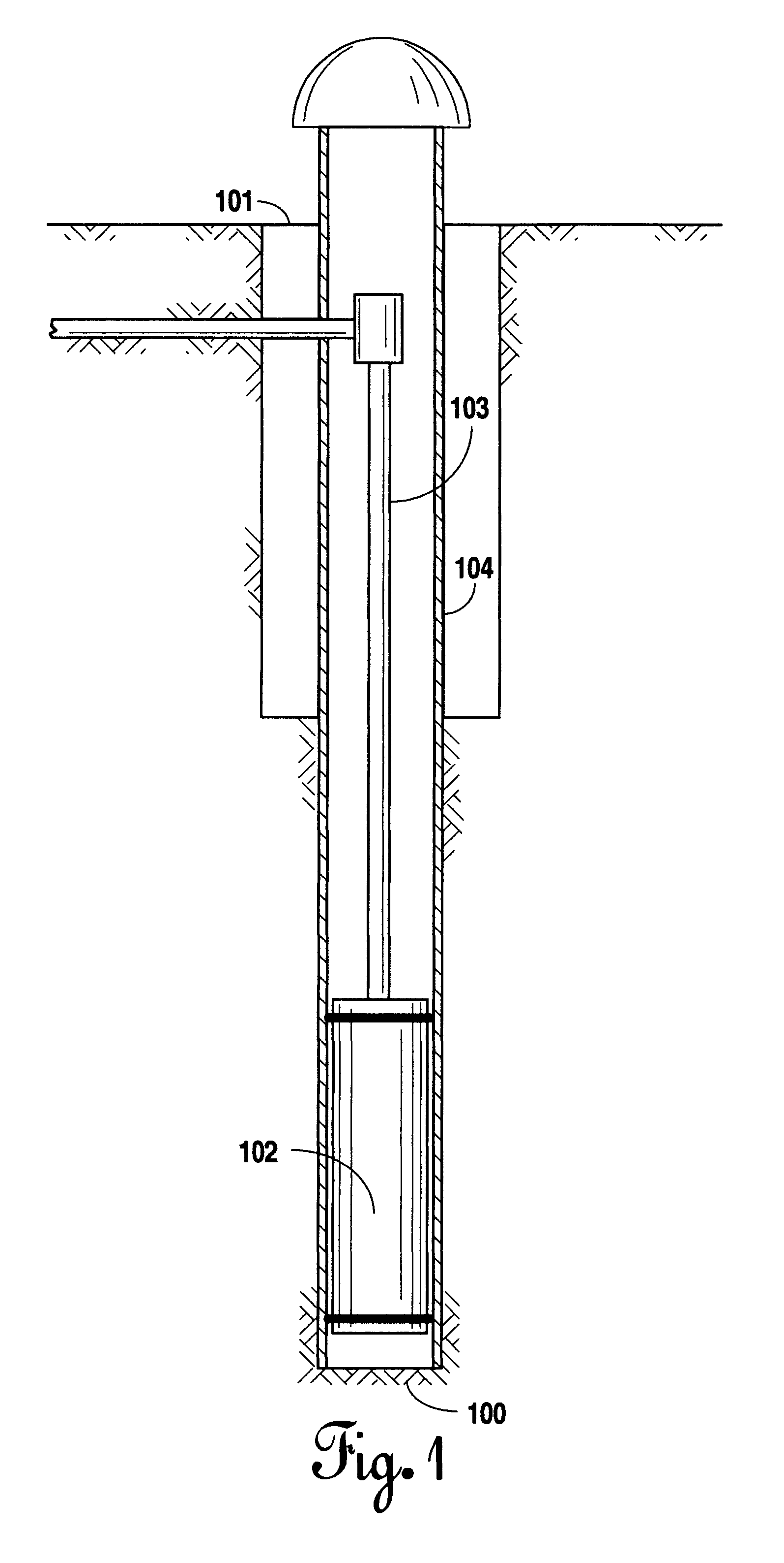
[0030]Referring to FIG. 1, a schematic of a typical water well where the present submersible pump drop pipe and casing could be used is illustrated. While the present invention can be useful in other obvious applications, the preferred use of the present invention is in water wells 101. The water well 101 may be drilled into an aquifer 100. The aquifer 100 is simply a water-bearing layer of sediment or rock with interconnected pore spaces or fractures that accumulate water. Upon drilling into the aquifer 100 the water well 101 is formed. Several components are inserted within the water well 101 which are necessary for its function. However, for purposes of the present invention, only certain key components will be addressed.

[0031]Within the water well 101 is placed casing 104 to keep the water well 101 open. Within the casing 104 and at the base of the water well 101 is inserted a submersible pump 102. Pump 102 is simply a motor or pump assembly that is designed to be placed entirel...


PUM

PropertyMeasurementUnit
diameteraaaaaaaaaa
diameteraaaaaaaaaa
lengthaaaaaaaaaa

Abstract

A submersible pump drop pipe and casing assembly and method of manufacture is disclosed. The drop pipe/casing has a seated connector and base. The seated connector has a first and second cylinder section, the first cylinder section being used to align and direct the base into the seated connector and to provide lateral strength to the pipe.

Description

[0001]This application is a divisional of U.S. patent application Ser. No. 09 / 989,512 filed on Nov. 20, 2001 (now U.S. Pat. No. 6,666,480 B2).BACKGROUND OF THE INVENTION[0002]1. Field of the Invention[0003]Applicant's invention relates to a submersible pump drop pipe and casing assembly connection and method of manufacture for use in water well and related systems.[0004]2. Background Information[0005]In water well systems, a casing is inserted into the well to maintain the structure of the well. Within the well is placed a submersible pump to which is attached a drop pipe which carries the water from within the well to the surface. It is important in this system that the drop pipe not leak. Therefore, in modern practice pipes are joined together with couplings and sealed with large amounts of either cement or “pipe dope” to prevent leaking. The positioning of the couplings can take a great deal of effort to do properly. In addition, pipe “dope” and cement have long curing times whic...

Claims


Application Information

Patent Timeline
Patent Type & Authority Patents(United States)
IPC IPC(8): F16L15/00E21B17/042E21B17/08
CPCE03B3/16E21B17/08E21B17/042Y10T29/49881
Inventor HANEY, MORRIS G.THEIN, ROY L.
Owner JOHNSON SCREENS
Why Eureka
Try Eureka