
Impact energy absorbing crash cushion

a technology of energy absorption and crash cushion, which is applied in the direction of vehicle body, roof, monocoque construction, etc., can solve the problems of weakest weak spot to ruptur

Inactive Publication Date: 2007-08-28
AKAD OSMAN E
View PDF24 Cites 30 Cited by
  • Summary
  • Abstract
  • Description
  • Claims
  • Application Information

AI Technical Summary

Benefits of technology

The system effectively dissipates impact energy through sequential breaking of weakened areas and fluid shearing, reducing the force of impact and enhancing passenger safety by decelerating vehicles during collisions.

Problems solved by technology

When an impact force is applied to the piston, the movement of the piston increases the pressure of the fluid within the chamber, which causes the weakest of the weak spots to rupture.

Method used


Image

  • Impact energy absorbing crash cushion
  • Impact energy absorbing crash cushion
  • Impact energy absorbing crash cushion

Examples


second embodiment

[0067]In this aspect of the second embodiment, a protective mesh can be provided in the openings 8 in order to prevent the inlet valve 10 from bending backwards.

[0068]As shown in FIG. 10, in either of the first and second embodiments of the crash cushion, escaping material from the cushion 3 can be directed back onto the impacting vehicle via an escape canal 7. By directing the material in this way, a portion of an oncoming vehicle's own impact force can be used against itself. Because the power of an oncoming vehicle is used against itself, there is a partial reversal of the incoming force.

[0069]Moreover, as shown in FIGS. 11A-11B, it is possible to use a nozzle 8′ (or multiple nozzles) for controlling the area of an orifice of an opening 8 in the back plate 1 of the second embodiment. The opening orifice area of these nozzles 8′ can be designed to change based on the pressure of material 4 escaping from the opening. Welded beams 82 can be used to hold the “C” rings 80 in place. Pl...

third embodiment

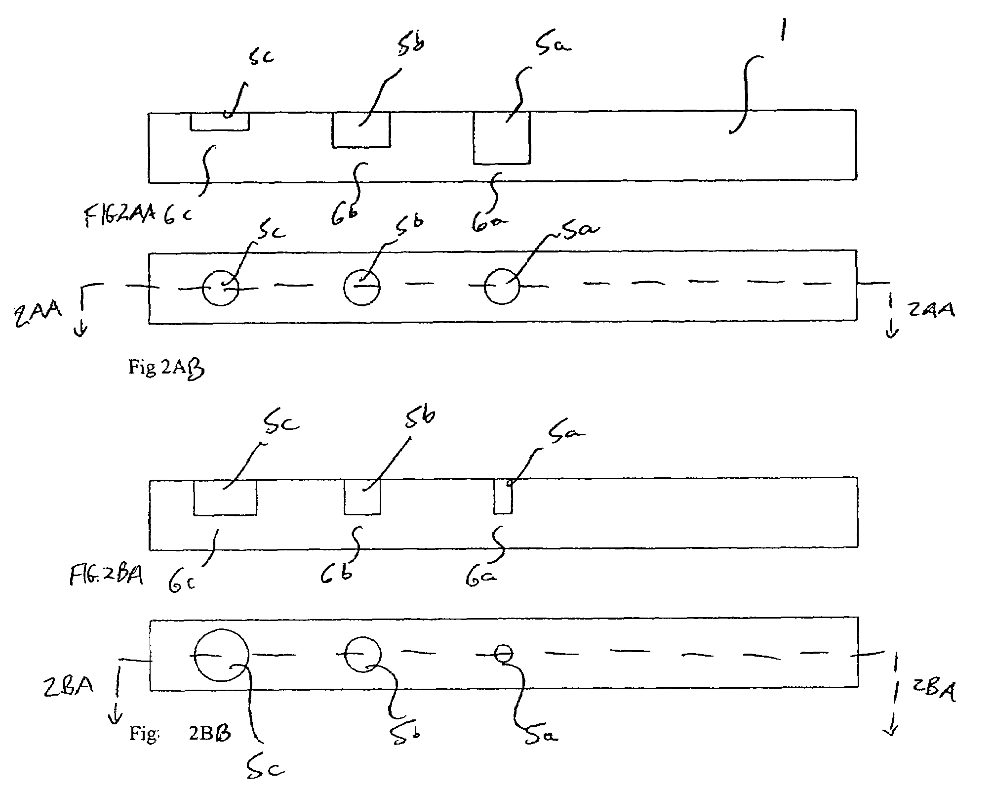
[0089]FIG. 26 shows the crash cushion 100″ in which a cushion 20 (e.g., a bag structure) has a wall structure with multiple layers 20a, 20b. As shown in FIGS. 27A-27C, each layer 20a, 20b, 20c contains one or multiple weakened areas 6′. These weakened areas 6′ can be varying depth recesses 5′ carved on the cushion 20. During an impact, pressurized material 4 within the cushion 20 would break open the weakened areas 6′, discharging fluid, or shearing fluid via weakened areas 6′.

[0090]As shown in FIG. 25, within the multiple layers 20a, 20b, 20c can be provided gel materials with different viscosities, but the invention is not limited in this respect. The different viscosity gel reservoirs 43a, 43b can be connected respectively to the reed valves. Thus, only the amount of energy of a single gel material will be dissipated when the reed valve opens. If the amount of energy exceeds that amount, then the reed valve for the next higher viscosity gel reservoir 43 functions. Therefore, the ...


PUM


Abstract

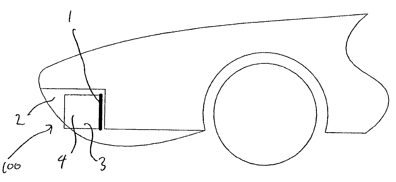
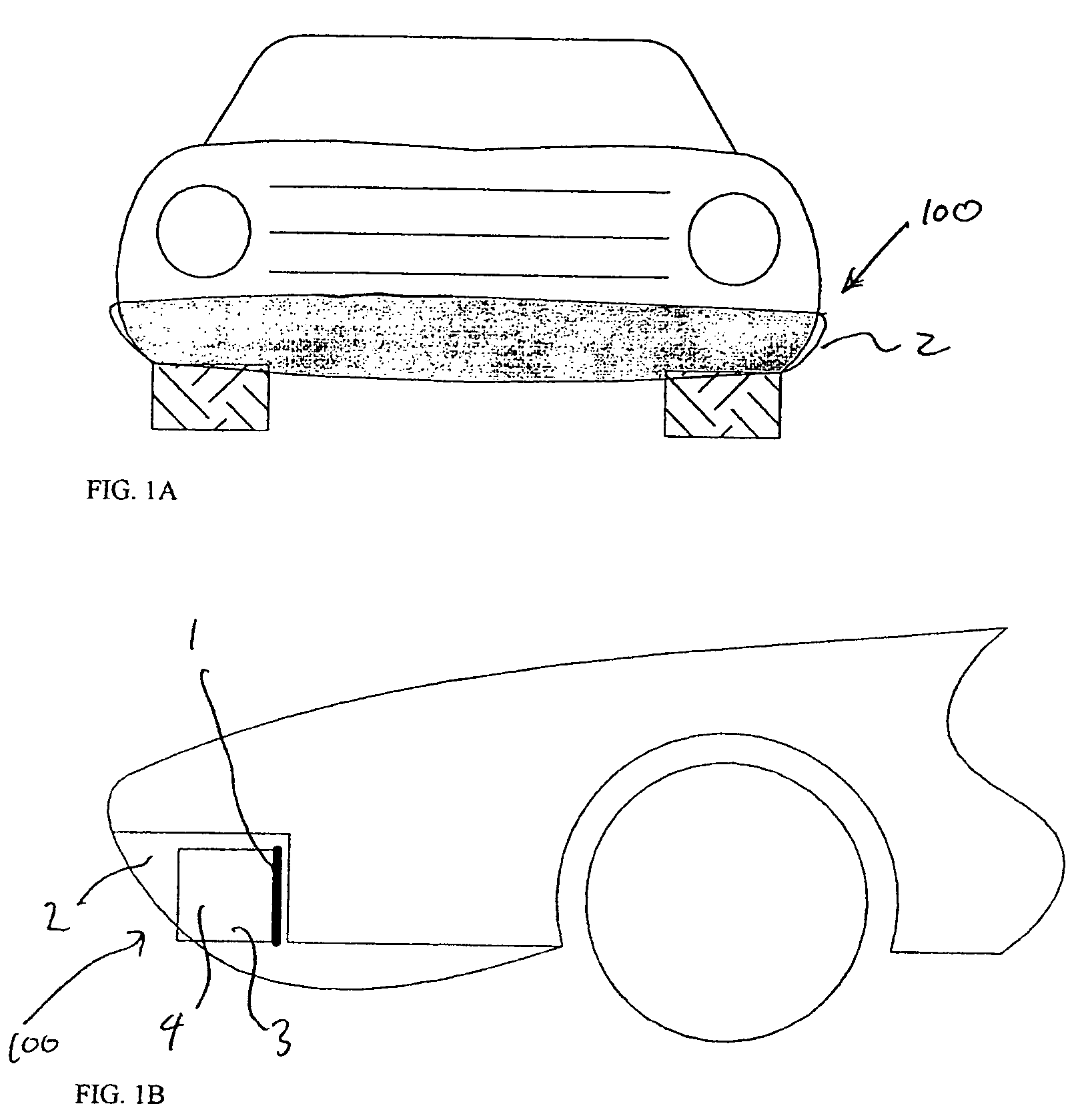
A crash cushion including a cushion filled with material; and a back plate including at least one recess communicating with a back of the cushion such that material from the cushion fills the recess; wherein the back plate is configured so that when a force is applied to said cushion, the material within the at least one recess breaks a portion of the bumper plate and exits the recess. A crash cushion including a cushion filled with material; a back plate, including at least one opening communicating with a back of the cushion such that the material from the cushion is capable of filling the recess; and at least one valve; wherein the at least one valve is configured so that when a force is applied to the cushion, a portion of the material within the cushion opens the valve and exits the cushion.

Description

BACKGROUND[0001]Existing vehicle bumpers can be filled with foam. The foam provides impact absorption when there is an impact between the vehicle and an object, such as another vehicle. However, the foam does sufficiently reduce the force of the impact.[0002]U.S. Pat. No. 6,148,970 discloses an energy absorbing system in which a piston travels within a fluid filled chamber, which has weak spots formed in a sequence along a length of the side wall of the chamber. When an impact force is applied to the piston, the movement of the piston increases the pressure of the fluid within the chamber, which causes the weakest of the weak spots to rupture. As the force is increased, the weak spots will rupture in sequence, providing a superior shock absorbing system.[0003]In addition, U.S. Pat. No. 6,695,104 discloses a reusable energy absorbing system similar to that in U.S. Pat. No. 6,148,970. In this system, the impact force on the piston causes a discharge of fluid through two-way valves fro...

Claims


Application Information

Patent Timeline
Patent Type & Authority Patents(United States)
IPC IPC(8): B60R19/22
CPCB60R19/20B60R21/276
Inventor AKAD, OSMAN E.
Owner AKAD OSMAN E
Learn More