Microneedle array module and method of fabricating the same

a technology of microneedle array and microneedle, which is applied in the direction of locomotives, transportation and packaging, paper/cardboard articles, etc., can solve the problems of drug not being absorbed very effectively by the vessel wall, process poses serious problems, and adverse medical effects on parts of the body

Inactive Publication Date: 2007-08-28
THE CLEVELAND CLINIC FOUND
View PDF26 Cites 36 Cited by
  • Summary
  • Abstract
  • Description
  • Claims
  • Application Information

AI Technical Summary

Problems solved by technology

But, this process has posed serious problems.
However, in some cases the drug may not be absorbed by the vessel walls very effectively.
In these cases, the drug may be caused to move downstream with the blood stream which may cause adverse medical effects to portions of the body not intended to receive the drugs, especially at such high concentrations.
The drugs may also be diluted in this delivery process and lose their effectiveness.
In any event, these relatively expensive drugs may not be achieving their intended purpose.
However, the stud protrusions of the balloon are not needles and thus, are not very efficient at puncturing the vessel walls, especially at depths adequate for injecting the specific drug.

Method used


Image

  • Microneedle array module and method of fabricating the same
  • Microneedle array module and method of fabricating the same
  • Microneedle array module and method of fabricating the same

Examples


Embodiment Construction

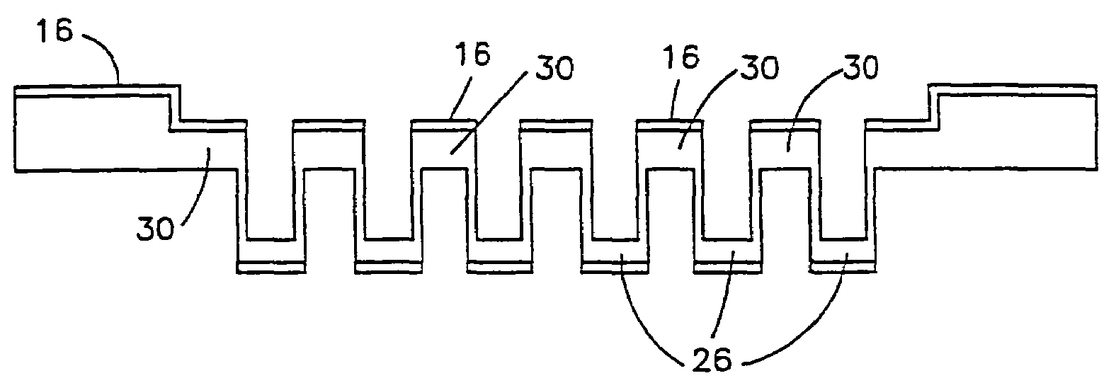
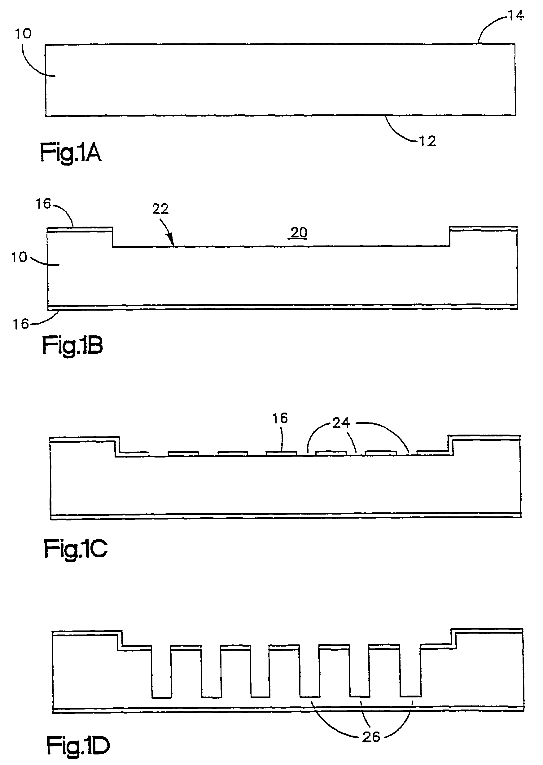
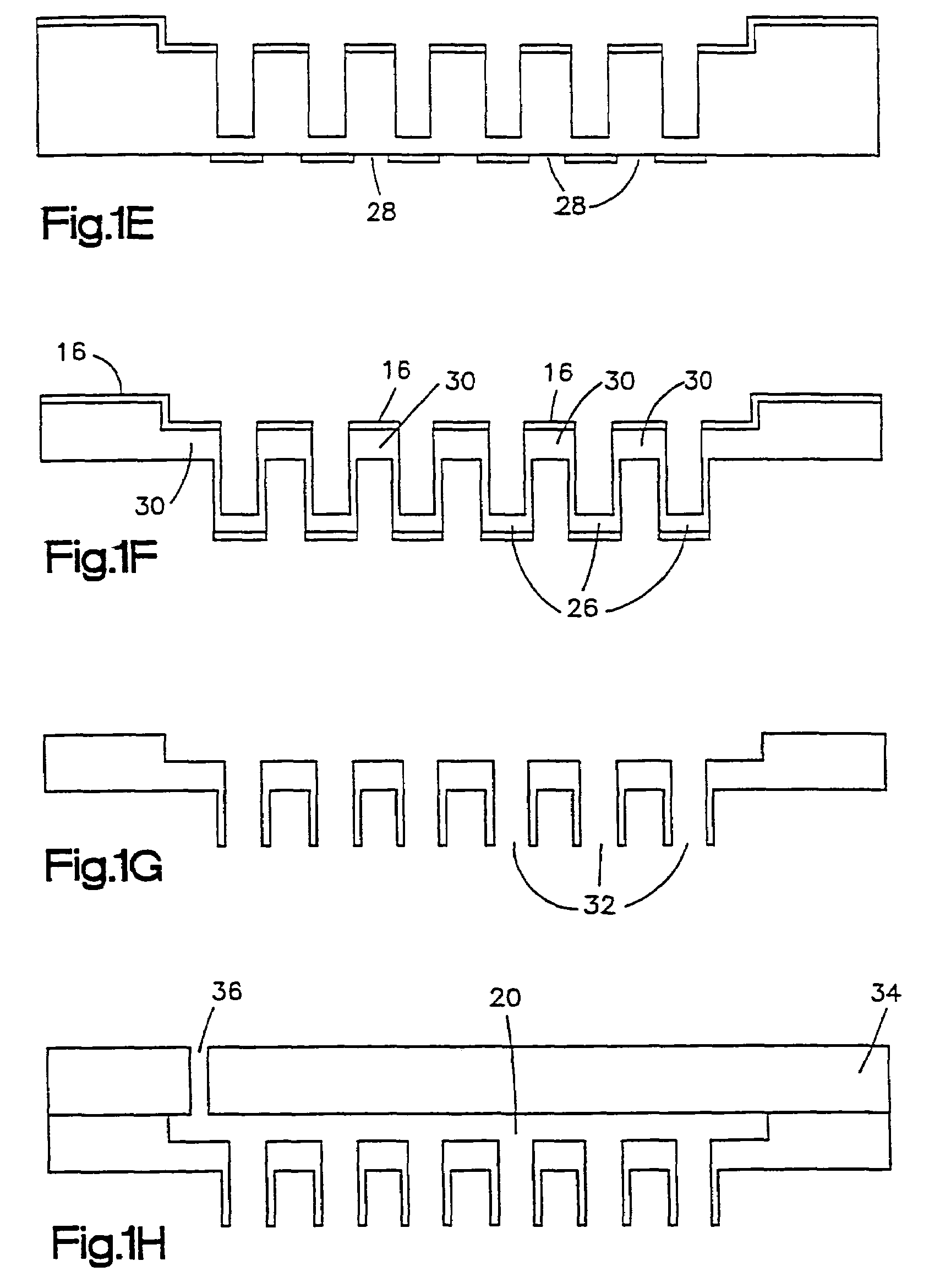
[0012]FIG. 1A-1H and FIGS. 2A-2G are illustrations of two exemplary methods of fabricating a microneedle array module. FIGS. 1G and 2F depict cross-sectional views of alternative embodiments of microneedle array structures having microneedles cylindrical in shape and conical in shape, respectively. The structures of FIGS. 1G and 2F result from their respective fabrication methods. FIGS. 3A and 3B depict two three-dimensional perspectives of the exemplary resulting microneedle array module shown in the cross-sectional view of FIG. 2F. FIGS. 1H and 2G provide cross sectional views of further embodiments of the array structure in which a reservoir well thereof is covered as will become better understood from the description found herein below.

[0013]In FIG. 1A is shown a substrate 10 having a front surface 12 and back surface 14. The substrate 10 may be comprised of Silicon or a glass material, or a form of SiO2, like pyrex, for example, and be on the order of four hundred micrometers (...


PUM

PropertyMeasurementUnit
thickaaaaaaaaaa
diameteraaaaaaaaaa
thickaaaaaaaaaa

Abstract

A microneedle array module is disclosed comprising a multiplicity of microneedles affixed to and protruding outwardly from a front surface of a substrate to form the array, each microneedle of the array having a hollow section which extends through its center to an opening in the tip thereof. A method of fabricating the microneedle array module is also disclosed comprising the steps of: providing etch resistant mask layers to one and another opposite surfaces of a substrate to predetermined thicknesses; patterning the etch resistant mask layer of the one surface for outer dimensions of the microneedles of the array; patterning the etch resistant mask layer of the other surface for inner dimensions of the microneedles of the array; etching unmasked portions of the substrate from one and the other surfaces to first and second predetermined depths, respectively; and removing the mask layers from the one and the other surfaces. One embodiment of the method includes the steps of: providing an etch resistant mask layer to the other surface of the substrate to a predetermined thickness; patterning the etch resistant mask layer of the other surface to define a reservoir region in the substrate; and etching away the unmasked reservoir region of the substrate to form a reservoir well in the other surface of the substrate. A layer of material may be provided to the other surface to enclose the reservoir well and a passageway is provided through the layer to the well region.

Description

[0001]This application is a continuation of U.S. patent application Ser. No. 10 / 162,848, filed on Jun. 5, 2002, now U.S. Pat. No. 6,790,372, which is a Divisional of U.S. patent application Ser. No. 09 / 643,103 filed Aug. 21, 2000 (now abandoned).BACKGROUND OF THE INVENTION[0002]The present invention is related to microelectromechanical systems (MEMS) and the fabrication thereof, in general, and more specifically, to a microneedle array module and its fabrication.[0003]Targeted drug delivery or the application of a high concentration of one or more drugs to a specific target area within the body has become of paramount importance to the fight against tumors, restentosis and similar life threatening medical conditions. Generally, these target areas are reachable through the walls of the blood vessels of the body. Present systems use a catheter with an imaging device to locate the target area. Once located, a specific drug or drugs are delivered to the targeted vessel wall area. But, t...

Claims


Application Information

Patent Timeline
Patent Type & Authority Patents(United States)
IPC IPC(8): H01L21/00B61C1/00A61M37/00B81C1/00H01R12/00
CPCA61M37/0015B81C1/00111A61M2037/003A61M2037/0038A61M2037/0053B81B2201/055
Inventor ROY, SHUVOFLEISCHMAN, AARON J.
Owner THE CLEVELAND CLINIC FOUND
Why Eureka
Try Eureka