Programmably sliceable switch-fabric unit and methods of use

a switch fabric and programmable technology, applied in the field of switch fabrics, can solve the problems of high cost of 3232 parts, inability to meet the demands of such a demanding situation, and the low-speed crossbar design of 44 mentioned above, and achieve the effect of scalable throughput speed and fault tolerance, and increased traffic throughput rate for a given line card/uni

Inactive Publication Date: 2007-08-28
PMC-SIERRA
View PDF2 Cites 28 Cited by
  • Summary
  • Abstract
  • Description
  • Claims
  • Application Information

AI Technical Summary

Benefits of technology

[0017]Briefly, under the switch fabric concept, each of a plurality of line cards (or other line units) can distribute its respective flows of communications traffic across a shared plurality of switching modules. Such switching modules may then switch or route the distributed traffic to others of the line cards / units according to dynamically-varied routing instructions. The traffic throughput rates that can be achieved for a given line card / unit may be increased by increasing the aggregate number of switching modules that service the given line card / unit. If one of the switching modules fails, others of the plural modules in the switch fabric may be used for moving the traffic through. A distributed switch fabric therefore provides the advantages of scalable throughput speed and fault tolerance.

Problems solved by technology

The 4×4 low-speed crossbar design mentioned above would probably not be appropriate for such a more demanding situation.
In practice, this kind of solution does not work for several reasons.
First, the 32×32 part tends to be much more expensive than the 8×8 switching device.
Discarding the use of the majority of resources on such an expensive, 32×32 part rarely makes economic sense.
Pricing in the 8×8 market may be such that use of a small subsection of the 32×32 part cannot be justified.
This can be prohibitively expensive.
This too can be prohibitively expensive, particularly if the software engineers had not had an earlier opportunity to learn and gain experience with the interface protocols of the replacement, 32×32 part.
The above situation leaves the industry with a host of unsolved problems.
It is difficult for manufacturers of switch-fabric units (e.g., switch-fabric chips) to efficiently manage their production schedules in view of changing market conditions.
It is difficult for manufacturers of switch-fabric systems (e.g., board-level integrators) to efficiently predict what sizes of inventory they will need for each different kind of SFU in order to meet changing market demands.
Support-staff education is therefore a problem in view of the changing needs in the different market segments (e.g., 4×4 to 32×32 or higher) and the different kinds of SFU's (switch-fabric units) that are supplied to each vertical market segment.

Method used


Image

  • Programmably sliceable switch-fabric unit and methods of use
  • Programmably sliceable switch-fabric unit and methods of use
  • Programmably sliceable switch-fabric unit and methods of use

Examples


Embodiment Construction

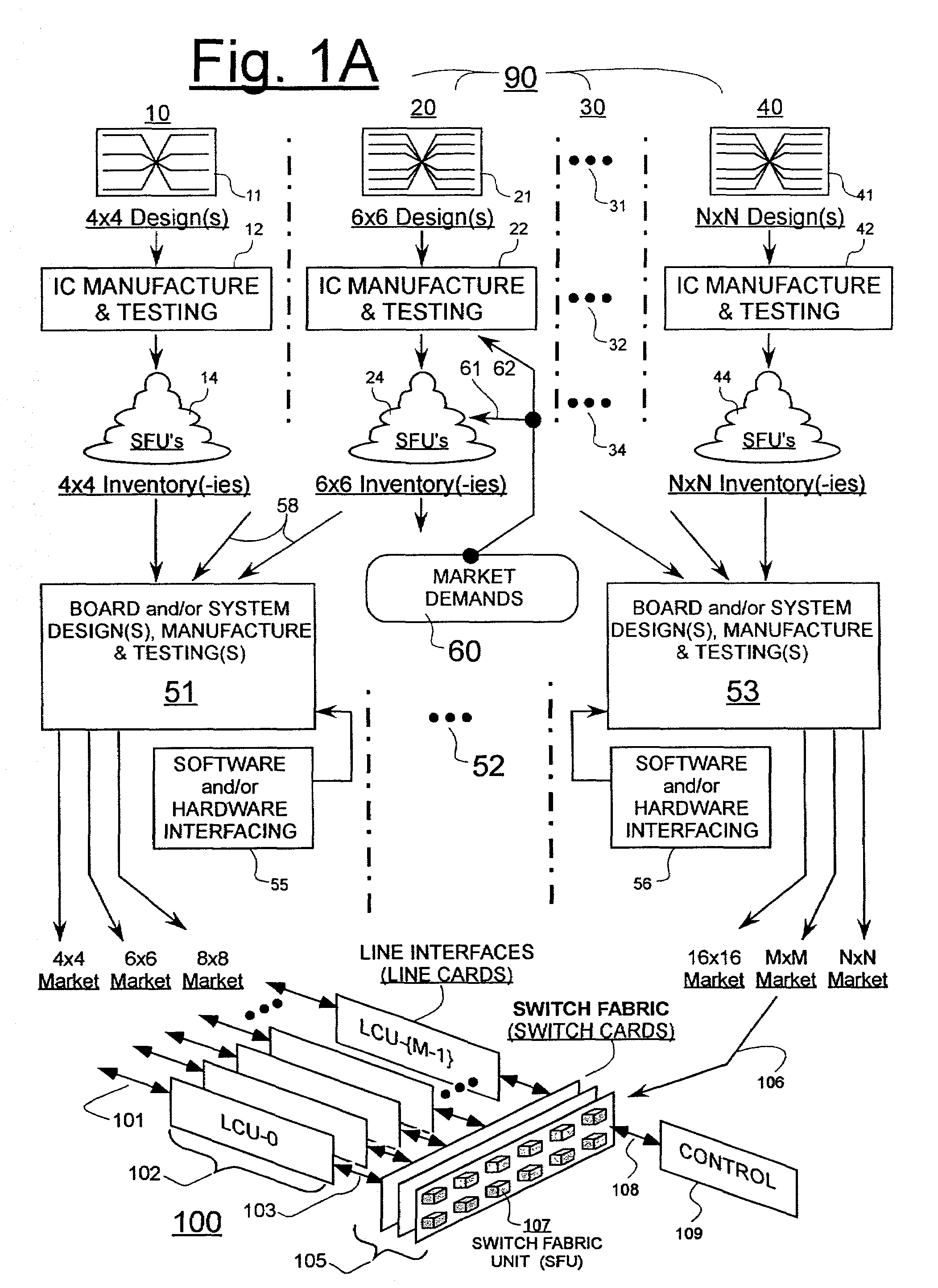
[0059]FIG. 1A is a workflow schematic for illustrating more clearly some of the industry problems described above. A first set (90) of parallel development paths 10, 20, . . . , 40 are illustrated as extending vertically to represent development and production cycles for different kinds of switch-fabric units (SFU's). Some overlap in shared technologies (e.g., integrated circuit fabrication processes) is of course possible between the illustrated parallel paths, 10-40.

[0060]One of the paths: 10, represents in downstream-directed order, the design-development, design-production, and supply-chain management phases of relatively simple class of SFU's, say, the 4×4 class of switch-fabric units. At the start of the 4×4 path 10, one or a variety of different 4×4 designs (11) may be created for servicing respective end-uses (100) that call for specific combinations of: (a) meeting a specified data throughput bandwidths, (b) complying with industry standard or proprietary interface protocol...


PUM


Abstract

A programmably sliceable switch-fabric unit (PSSU) and methods of use are disclosed. An N×N′ switch matrix is programmably made to operate as if it were a plurality of S×S′ virtual switch slices, where S<N and S′<N′. Ingressing requests each specify an egress path (unicast mode) or plural egress paths (multicast mode) in terms of one or more relative egress port numbers. A request translator converts relative egress port numbers into absolute egress port numbers by determining what virtual slice each request belongs to. The translated egress requests are handed off to an arbitration and/or scheduling mechanism for further processing. If the translated request is granted, the corresponding payload egresses through the actual egress port(s) which the translated request asked for. An inventory of PSSU's may be distributed in accordance with the disclosure to segmented markets such that each PSSU can service the specific needs of a market, be it providing a plurality of 4×4 switch slices, 8×8 switch slices, 16×16 switch slices, or otherwise. In one embodiment, virtual slices are distributed throughout a physical switch-matrix so as to minimize pinout crossover for external line card units.

Description

1. FIELD OF DISCLOSURE[0001]The present disclosure of invention relates generally to switch fabrics such as may be found in packet-based (or cell-based, or like framed-data based) digital, telecommunication switching systems.[0002]The disclosure relates more specifically to switch-fabric units (SFU's) which may be integrated in the form of packaged, monolithic integrated circuits (switch-fabric chips) or otherwise, and provided in repeated form within a switch fabric of a digital, telecommunication switching system.2a. CROSS REFERENCE TO CO-OWNED APPLICATIONS[0003]The following copending U.S. patent applications are owned by the owner of the present application, and their disclosures are incorporated herein by reference:[0004](A) Ser. No. 09 / 847,711, filed May 1, 2001 by Onchuen (Daryn) Lau, Chris D. Bergen, et al, and which is originally entitled, MULTISERVICE SWITCHING SYSTEM WITH DISTRIBUTED SWITCH FABRIC;[0005](B) Ser. No. 09 / 846,875, filed May 1, 2001 by Matthew D. Ornes, Chris...

Claims


Application Information

Patent Timeline
Patent Type & Authority Patents(United States)
IPC IPC(8): H04Q11/00
CPCH04Q3/521H04Q3/68H04Q2213/1302H04Q2213/1304H04Q2213/1305H04Q2213/13056H04Q2213/13076H04Q2213/1334H04Q2213/13341
Inventor ORNES, MATTHEW D.NORRIE, CHRISTOPHER I. W.CHUI, GENE K.LAU, ONCHUEN DARYN
Owner PMC-SIERRA
Why Eureka
Try Eureka