Vacuum clamping detection method and vacuum clamping detector

a detection method and vacuum clamping technology, applied in the direction of fluid pressure measurement, instruments, manufacturing tools, etc., can solve the problems of difficult to use the apparatus, the drop of the workpiece cannot be recognized during the transfer, and the recognition of the drop by the image sensor is generally too expensive to be attached

Inactive Publication Date: 2007-09-04
KOGANEI
View PDF11 Cites 49 Cited by
  • Summary
  • Abstract
  • Description
  • Claims
  • Application Information

AI Technical Summary

Benefits of technology

[0017]By operating the apparatus controller, the timing of the drop recognition for the suction detection apparatus can be changed freely.

Problems solved by technology

Therefore, even if the workpiece drops during the transfer and the sucker becomes in a state of sucking nothing, the negative pressure value of the suction / release passage is not reduced below the suction preparation pressure Pset, so that the drop of the workpiece cannot be recognized during the transfer.
However, drop recognition by the image sensor is generally too expensive to be attached to a general-purpose suction / transfer apparatus, so that such an apparatus is difficult to use actually.

Method used


Image

  • Vacuum clamping detection method and vacuum clamping detector
  • Vacuum clamping detection method and vacuum clamping detector
  • Vacuum clamping detection method and vacuum clamping detector

Examples


Embodiment Construction

[0024]Hereinafter, embodiments of the present invention will be described in details with reference to the accompanying drawings.

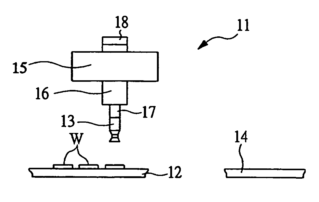
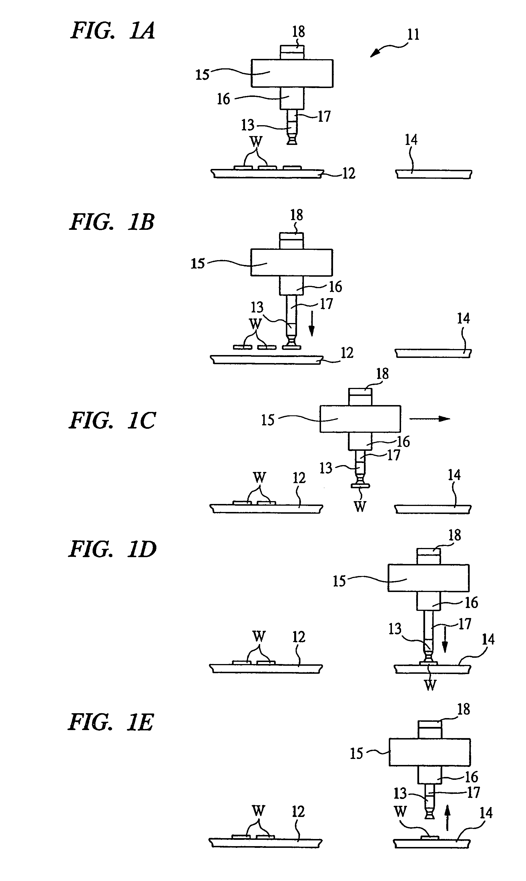
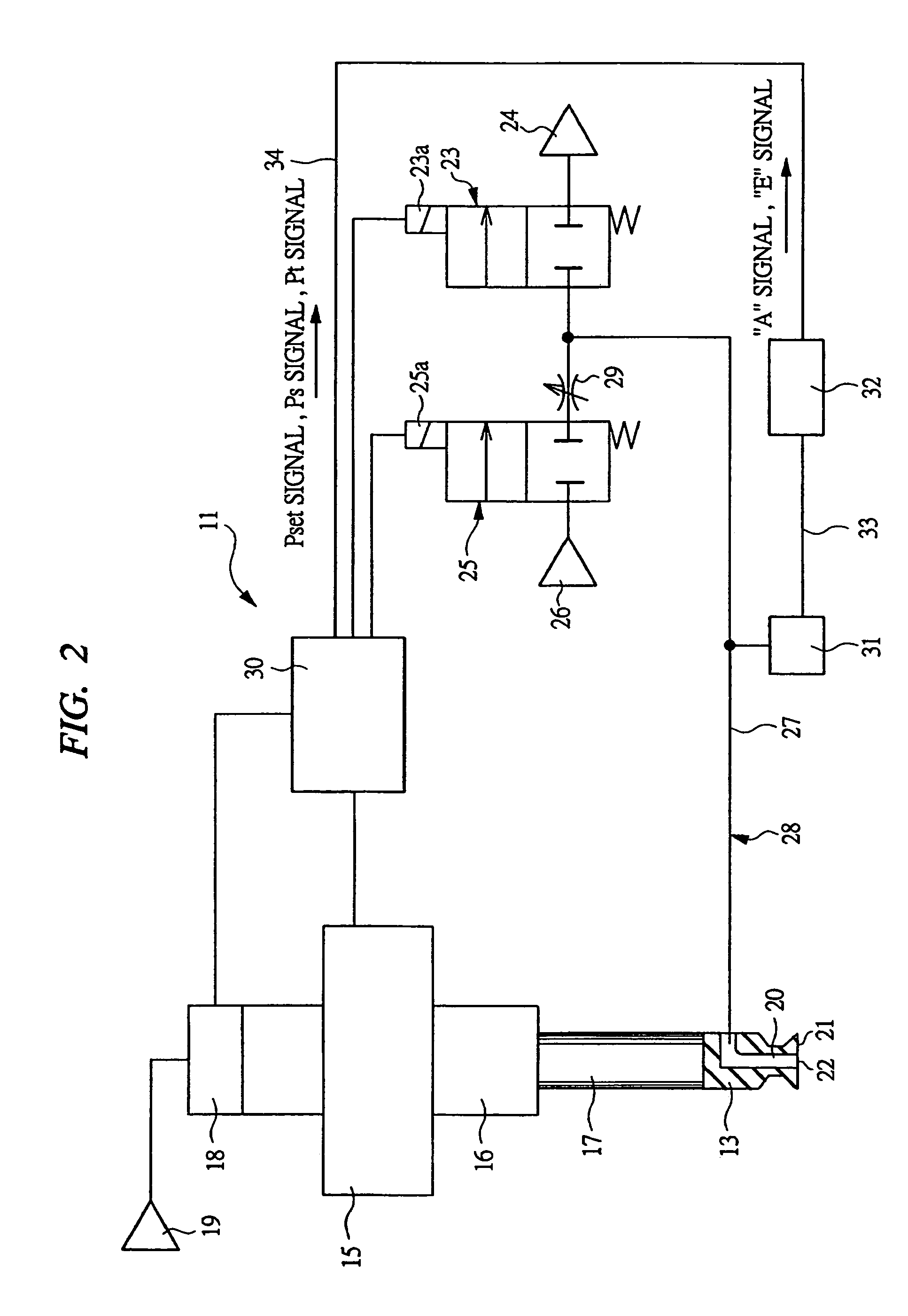
[0025]FIGS. 1A to 1E are explanatory diagrams showing a transfer procedure for sucking and transferring a workpiece by a vacuum-suction / transfer apparatus equipped with a suction detection apparatus according to an embodiment of the present invention, and FIG. 2 is a block diagram showing schematically the vacuum-suction / transfer apparatus shown in FIG. 1.

[0026]As shown in FIGS. 1A to 1E, this vacuum-suction / transfer apparatus 11 transfers, as workpieces W, electronic components such as ICs disposed on a component supply stage 12 to a printed circuit board 14 by sucking them using a sucker 13.

[0027]This vacuum-suction / transfer apparatus 11 has a horizontally movable carrying head 15, so that the carrying head 15 can be driven horizontally between the component supply stage 12 and the printed circuit board 14 by an unshown electronic motor etc. A pneumatic ...


PUM

PropertyMeasurementUnit
pressureaaaaaaaaaa
suction detectionaaaaaaaaaa
pressureaaaaaaaaaa

Abstract

When suction / release-passage-internal pressure Pin is equal to or less than a suction detection pressure Pj, a suction of a workpiece is detected and a transfer operation is started. As long as the suction / release-passage-internal pressure Pin does not rise to pressure having an upper limit value or more of the drop detection range during a transfer, it is recognized that the workpiece is not dropped from the sucker. The drop detection range is computed by adding predetermined allowable deflection width ΔD to the suction / release-passage-internal pressure Pin that is read as reference pressure under the condition that the workpiece is sucked by the sucker.

Description

CROSS REFERENCE TO RELATED APPLICATIONS[0001]This application claims the benefit of PCT Application No. PCT / JP2004 / 007567, filed on May 26, 2004 and Japanese Patent Application No. 2003-148948, filed May 27, 2003, the disclosures of which are herein incorporated by reference in their entirety.TECHNICAL FIELD [0002]The present invention relates to a suction detection method and a suction detection apparatus for detecting suction of a workpiece, the suction detection method and apparatus being effectively used for a vacuum-suction / transfer apparatus for transferring, as a workpiece, an electronic component such as IC and LSI to a test instrument, a printed circuit board or the like by vacuum suction.BACKGROUND OF THE INVENTION[0003]Many electronic components including an IC, LSI or the like in which a semiconductor integrated circuit is formed are placed on the test instrument, and whether each electronic component has a predetermined function is tested. At this time, each electronic ...

Claims


Application Information

Patent Timeline
Patent Type & Authority Patents(United States)
IPC IPC(8): H05K3/30B23Q7/04B25J15/06B65G47/91H01L21/683H05K13/04H05K13/08
CPCB25J15/0616B65G47/917H05K13/0413H01L21/6838Y10T29/53178H05K13/082H05K13/0815
Inventor TAKAHASHI, YUJI
Owner KOGANEI
Why Eureka
Try Eureka