
Slot cavity

a technology of slot cavity and cavity wall, which is applied in the direction of gas removal, borehole/well accessories, transportation and packaging, etc., can solve the problems of more extensive development and use of methane gas deposits

Inactive Publication Date: 2007-09-04
EFFECTIVE EXPLORATION
View PDF432 Cites 39 Cited by
  • Summary
  • Abstract
  • Description
  • Claims
  • Application Information

AI Technical Summary

Benefits of technology

[0003]The present invention provides a slot cavity that substantially eliminates or reduces at least some of the disadvantages and problems associated with previous cavities used in subterranean exploration.
[0006]Technical advantages of particular embodiments of the present invention include the formation of a slot-shaped cavity in a subterranean zone to provide a target for the intersection of an articulated well bore with a vertical well bore. The slot cavity has a cross-sectional area for intersection approximately equal to a cross-sectional cavity of other types of enlarged cavities which may be formed within the subterranean zone, such as generally cylindrical cavities. However, the volume of the slot cavity is generally less than the volume of other types of cavities such that the formation of the slot cavity requires less time and expense than the formation of other types of cavities.
[0007]Another technical advantage of particular embodiments of the present invention includes forming a slot cavity at least partially within a subterranean zone such that slot cavity intersects fractures of the subterranean zone. Intersecting the fractures with the slot cavity enables compositions included in or flowing through the fractures to be released into the slot cavity and drained to the surface. Thus, particular embodiments provide an improved method for accessing and draining compositions such as methane gas contained within a subterranean zone.

Problems solved by technology

Subterranean deposits of coal contain substantial quantities of entrained methane gas limited in production in use of methane gas from coal deposits has occurred for many years.
Substantial obstacles, however, have frustrated more extensive development and use of methane gas deposits in coal seams.

Method used


Image

  • Slot cavity
  • Slot cavity
  • Slot cavity

Examples


Embodiment Construction

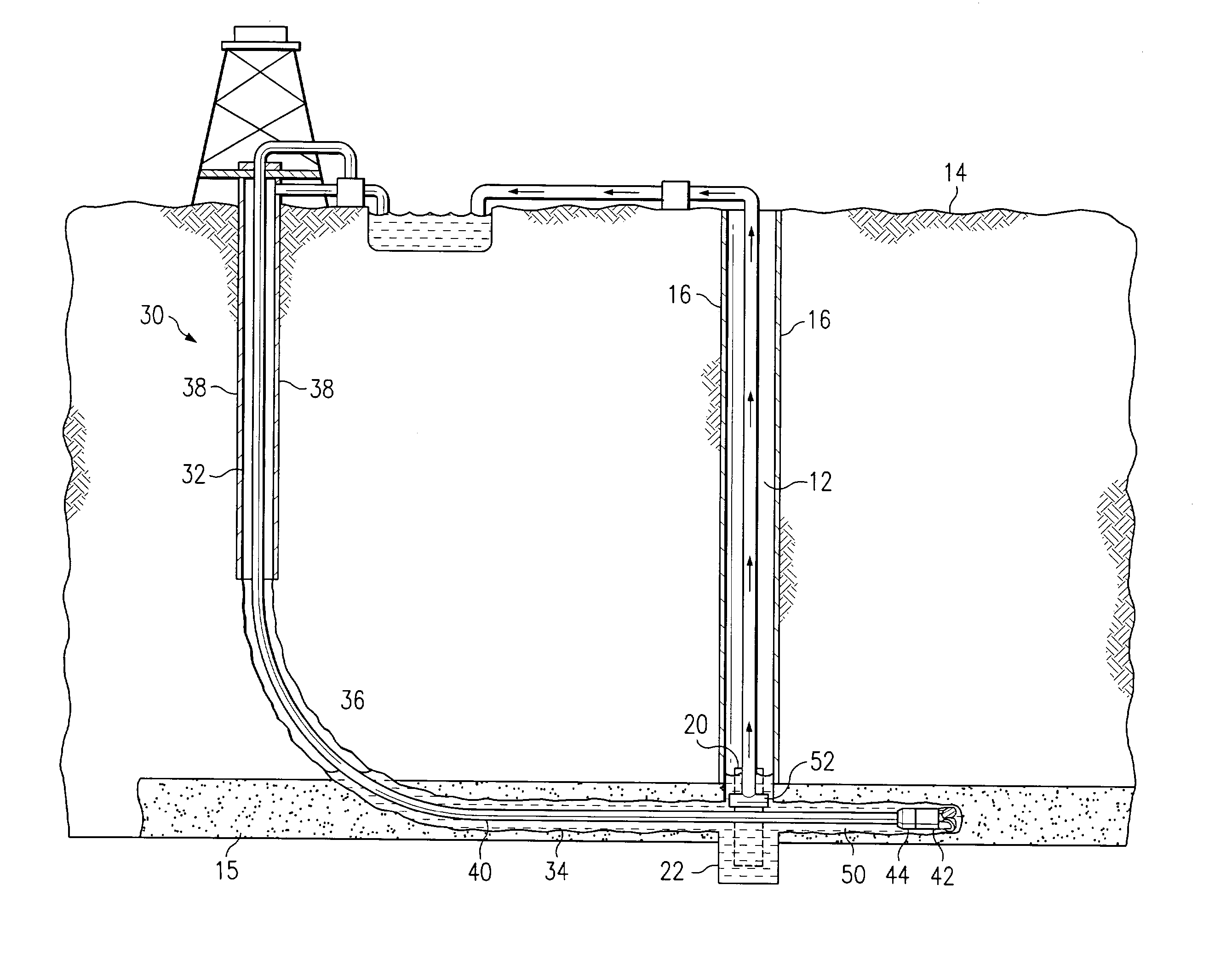
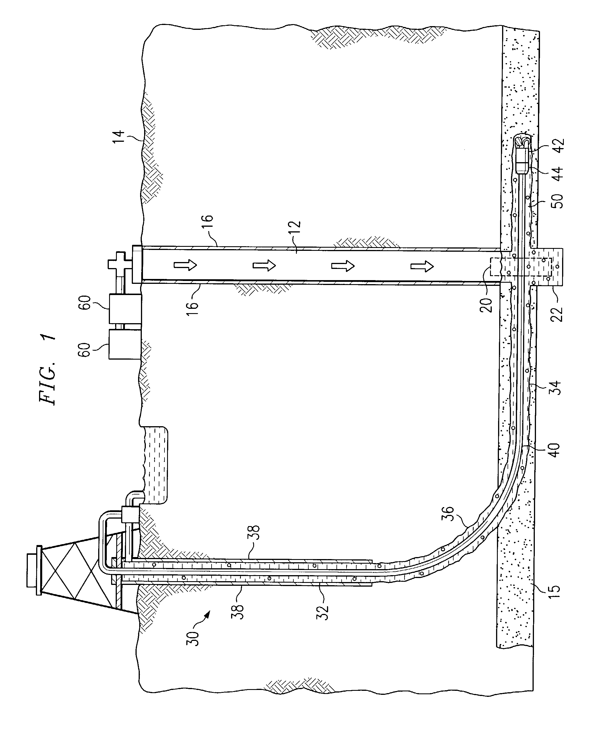
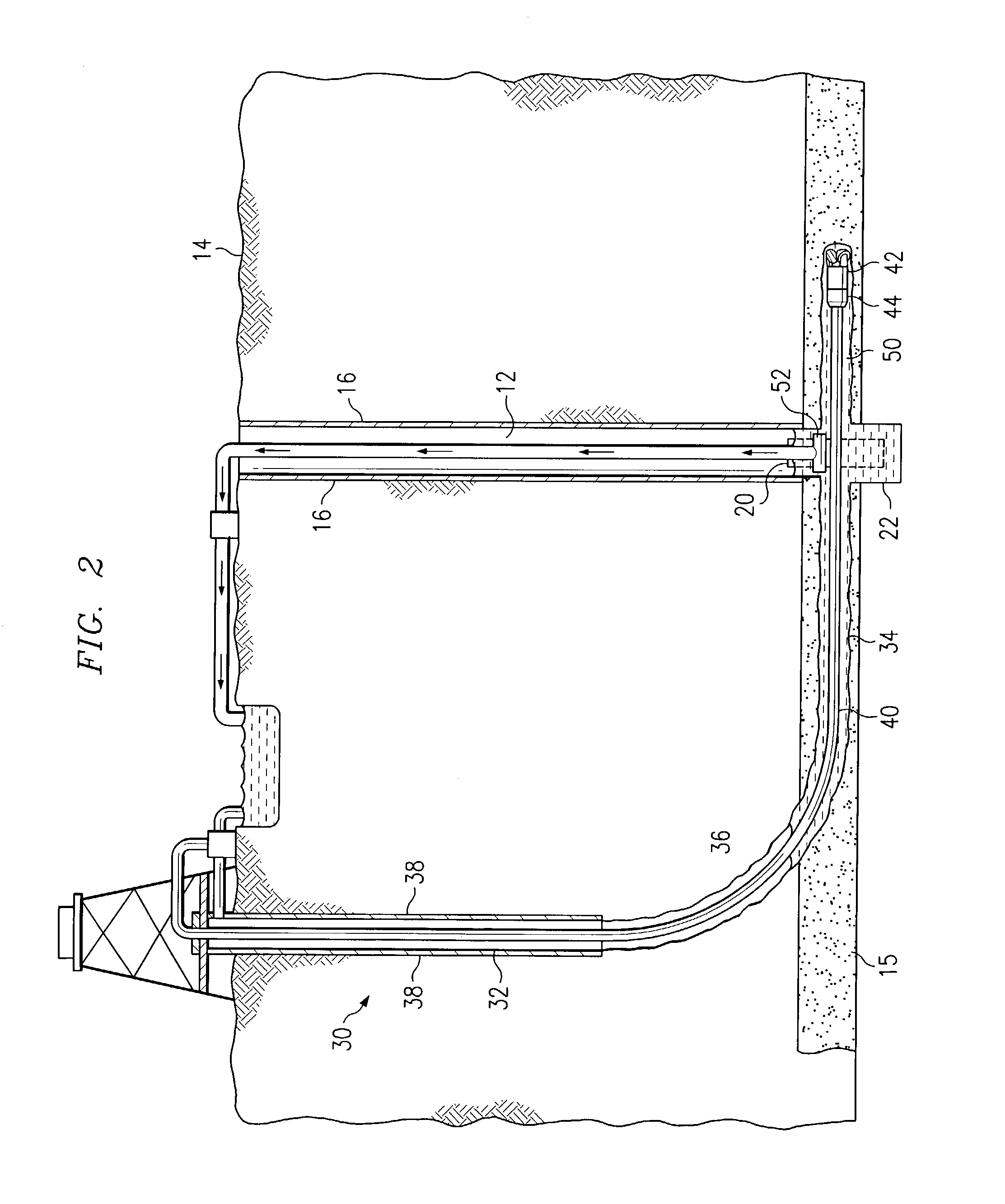
[0019]FIG. 1 illustrates an example dual well system for accessing a subterranean zone from the surface. In one embodiment, the subterranean zone may comprise a coal seam. In another embodiment, the subterranean zone may comprise an oil reserve. It will be understood that other subterranean zones can be similarly accessed using the dual well system of the present invention to remove and / or produce water, hydrocarbons and other fluids in the zone and to treat minerals in the zone prior to mining operations.

[0020]Referring to FIG. 1, a substantially vertical well bore 12 extends from a surface 14 to a target layer subterranean zone 15. Substantially vertical well bore 12 intersects, penetrates and continues below subterranean zone 15. Substantially vertical well bore 12 may be lined with a suitable well casing 16 that terminates at or above the level of the coal seam or other subterranean zone 15.

[0021]A slot cavity 20 may be formed in substantially vertical well bore 12 at the level ...


PUM


Abstract

A method for accessing a subterranean zone from the surface includes drilling a substantially vertical well bore from the surface to the subterranean zone and forming a slot cavity in the substantially vertical well bore proximate to the subterranean zone. The slot cavity comprises a substantially non-cylindrical shape. The method also includes drilling an articulated well bore from the surface to the subterranean zone. The articulated well bore is horizontally offset from the substantially vertical well bore at the surface and intersects the substantially vertical well bore at a junction proximate to the subterranean zone. The method may include drilling the articulated well bore to intersect the slot cavity of the substantially vertical well bore and drilling a substantially horizontal drainage pattern from the slot cavity into the subterranean zone. The subterranean zone may comprise a coal seam.

Description

TECHNICAL FIELD OF THE INVENTION[0001]The present invention relates generally to the field of subterranean exploration, and more particularly to a slot cavity.BACKGROUND OF THE INVENTION[0002]Subterranean deposits of coal contain substantial quantities of entrained methane gas limited in production in use of methane gas from coal deposits has occurred for many years. Substantial obstacles, however, have frustrated more extensive development and use of methane gas deposits in coal seams. Dual well systems have been used to aid in producing the methane gas from the coal seams. Such dual well systems may include two wellbores that intersect at a junction. In particular cases, an enlarged, cylindrical cavity is formed at a proposed junction to act as a target for the intersection of the wellbores.SUMMARY OF THE INVENTION[0003]The present invention provides a slot cavity that substantially eliminates or reduces at least some of the disadvantages and problems associated with previous cavi...

Claims


Application Information

Patent Timeline
IPC IPC(8): E21B43/30E21B43/00E21F7/00
CPCE21B43/006E21B43/305E21F7/00
Inventor ZUPANICK, JOSEPH A.RIAL, MONTY H.
Owner EFFECTIVE EXPLORATION
Learn More