Side entry sub hydraulic wireline cutter and method

a sub-hydraulic wireline cutter and cutting method technology, which is applied in the direction of drilling casings, drilling pipes, borehole/well accessories, etc., can solve the problems of insufficient time to extract the entire length of wireline b>15/b> from the wellbore, uncontrollable situation of the well, and inability to provide sufficient pulling force on the wireline, etc., to achieve the effect of increasing the differential pressure and being easily located

Inactive Publication Date: 2007-09-04
BAKER HUGHES HLDG LLC
View PDF7 Cites 73 Cited by
  • Summary
  • Abstract
  • Description
  • Claims
  • Application Information

AI Technical Summary

Benefits of technology

[0009]Optionally a ridge can be provided on the rod where the diameter of the second section is greater than the diameter of the first section. The ridge provides the capability of increasing the differential pressure across the first piston as the first piston passes across the ridge. Additional options include a fishing neck and a hanging plate disposed on the line cutting assembly. The hanging plate would provide one method by which the internal cutting assembly could easily be located with the pipe connection, to allow the wireline to be cut at the correct position. The fishing neck would allow the entire cutting assembly to be removed from the drillpipe, if at any time during the operation, it becomes necessary to gain access to the drillpipe, by passing logging tools down the drillpipe and below the side entry sub. In addition, the optional use of the extension arm and the wireline grapple would allow a severed wireline to immediately be caught by slips, to grapple the line.

Problems solved by technology

However, since the downhole tool 16 is often thousands of feet below the entrance to the wellbore 5, and can be at depths exceeding 25,000 feet, there may not be sufficient time to extract the entire length of wireline 15 from the wellbore 5 before the well reaches an uncontrollable situation.
Alternatively, in some deep and deviated wells it may be impossible to provide sufficient pulling force on the wireline 10 to release it from the toolstring 16.
This generally permanently damages the well such that it cannot be recovered.
Any failure of the shear rams may also result in loss of a rig and significant risk to operational personnel at the wellsite.

Method used


Image

  • Side entry sub hydraulic wireline cutter and method
  • Side entry sub hydraulic wireline cutter and method
  • Side entry sub hydraulic wireline cutter and method

Examples


Embodiment Construction

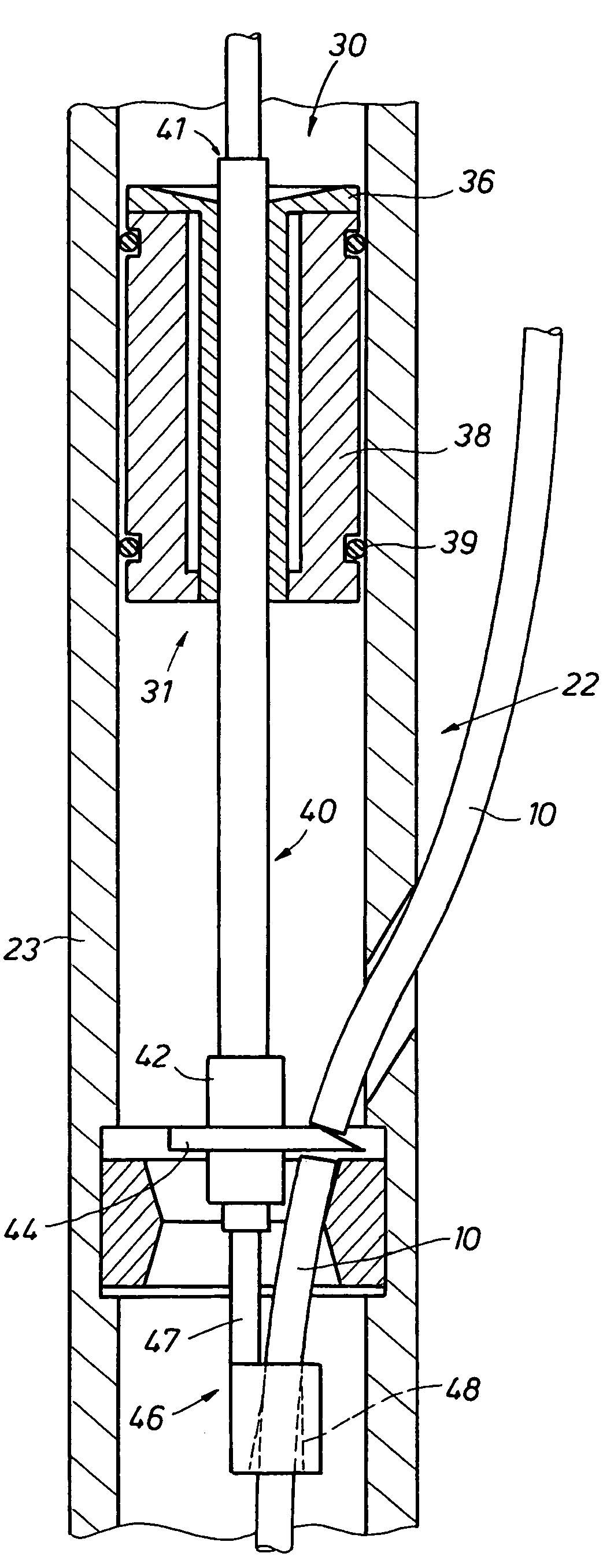
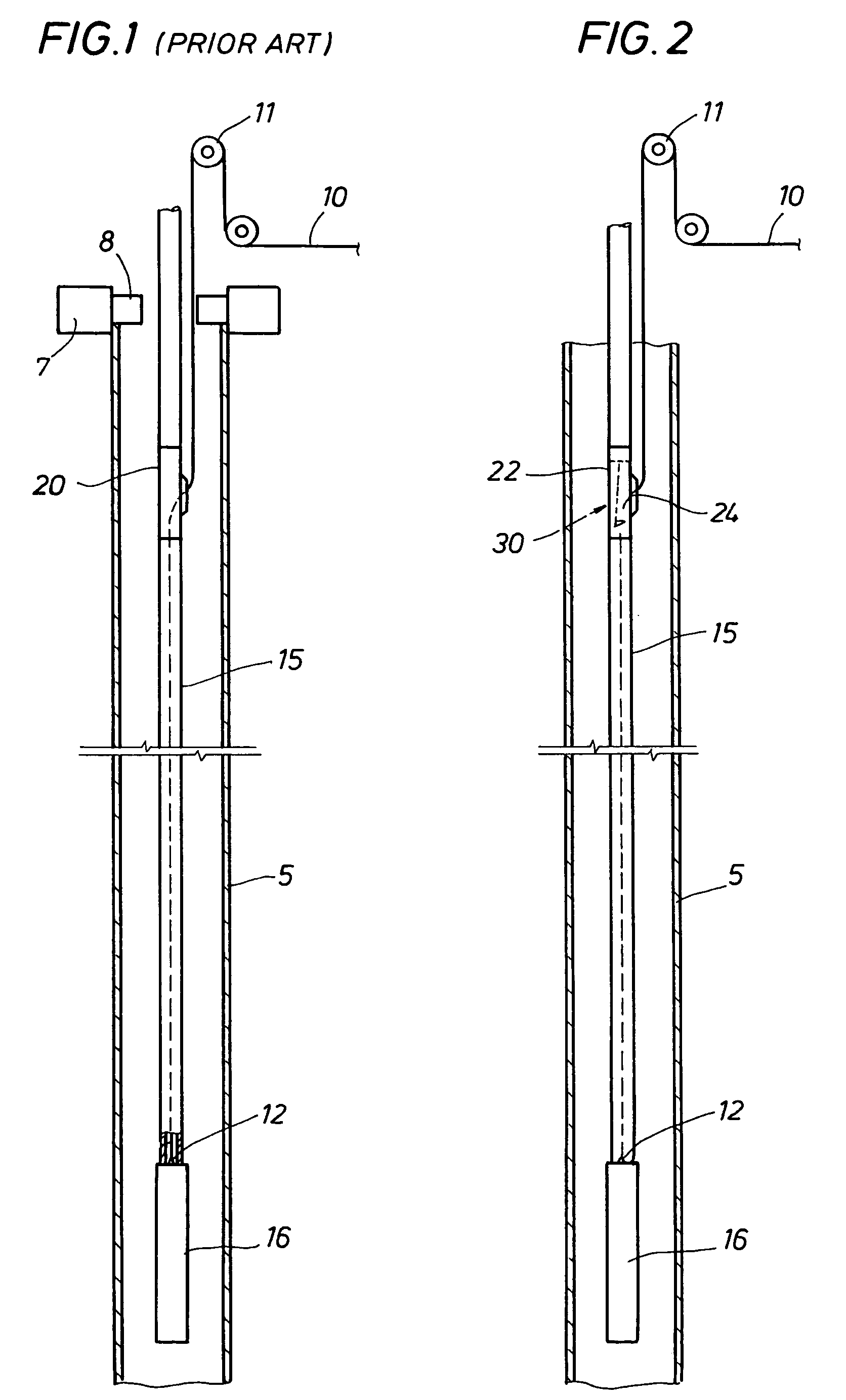
[0018]With reference to the drawing herein, one embodiment of pipe string 15 having a side entry sub 22 with a cutter mechanism 30 is disclosed in FIG. 2. Here the pipe string 15 is disposed within a wellbore 5 and further includes a downhole tool 16 secured to one of its ends. The downhole tool 16 can be any one of a number of tools used in exploration or production of hydrocarbons within wellbores, such as perforating guns, well logging devices, or any other device used in combination with a pipe string in a wellbore. More specifically, the present invention is useful for downhole tools 16 that include the use of a wireline to perform their tasks.

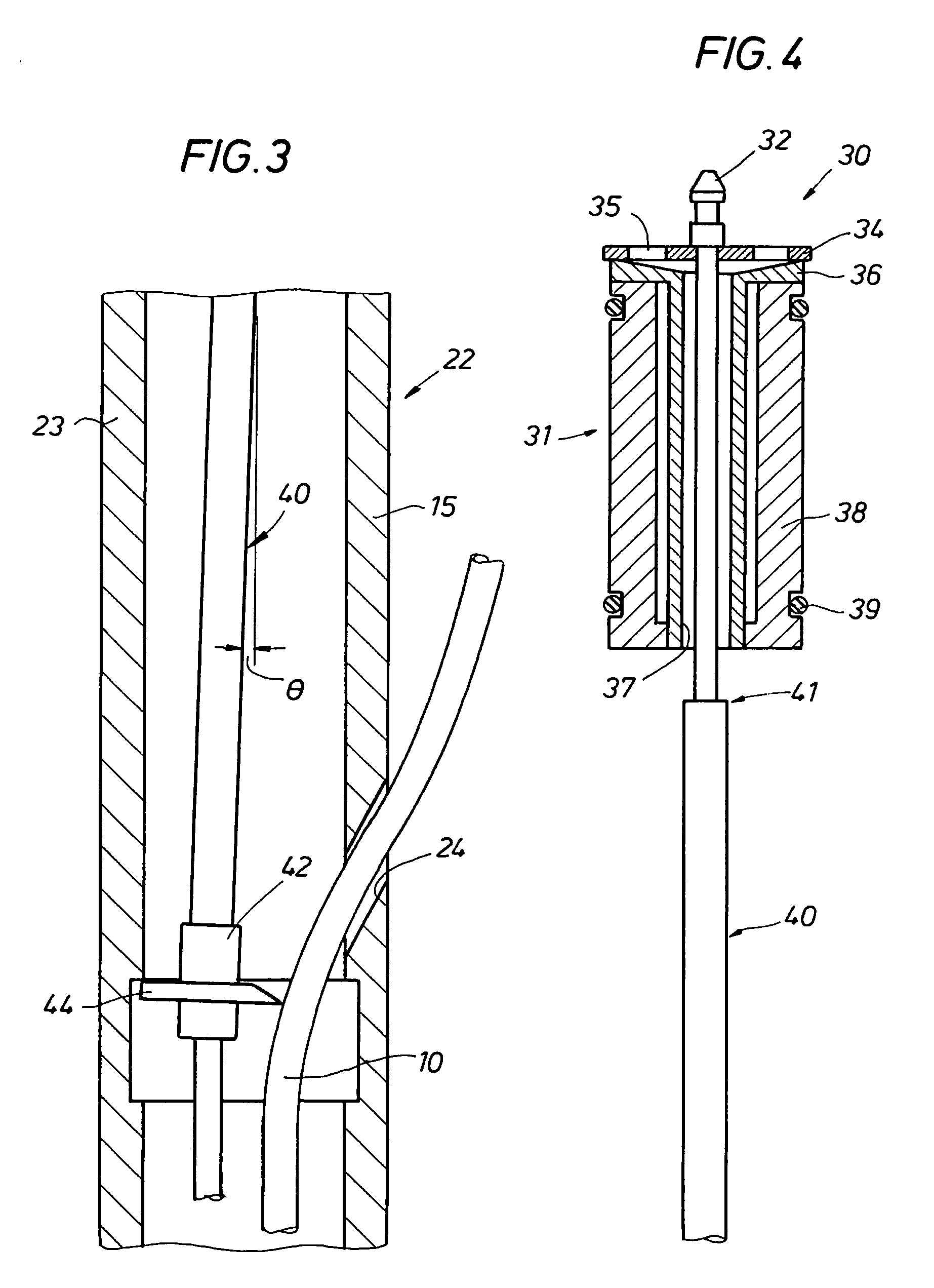
[0019]As shown in FIG. 2 a wireline 10 is connected at the downhole tool 16 at a cable head 12, is disposed within the pipe string 15 from the cable head 12 up to the side entry sub 22, where it exits from the inside of the pipe string 15 through an aperture 24 formed in the wall of the side entry sub 22. The type and design of the side e...


PUM


Abstract

A side entry sub for use with a drill string, where the side entry sub receives a wireline within its inner diameter. The present invention includes a device capable of severing the wireline proximate to the side entry sub. The present invention can further include a capturing device to grapple the severed portion of the wireline to prevent it from being dropped within the wellbore.

Description

BACKGROUND OF THE INVENTION[0001]1. Field of the Invention[0002]The invention relates generally to the field of exploration and production of hydrocarbons from wellbores. More specifically, the present invention relates to a method and apparatus to operate tubing and pipe conveyed downhole tools within a wellbore. Yet even more specifically, the present invention relates to a method and apparatus to operate tubing and pipe conveyed downhole tools within a wellbore further including a wireline secured to the downhole tool. The apparatus and method of the present invention further relates to the ability to sever the wireline such that the severed portion above the incision can be removed from the wellbore in a relatively short amount of time.[0003]2. Description of Related Art[0004]One of the primary uses of the present invention occurs within a wellbore, therefore in describing the present invention, the terms “top” and “above” mean closer to the entrance of the wellbore, whereas the...

Claims


Application Information

Patent Timeline
Patent Type & Authority Patents(United States)
IPC IPC(8): E21B29/04E21B17/02E21B31/16
CPCE21B17/025E21B29/04E21B31/16
Inventor WILLS, PHILIP
Owner BAKER HUGHES HLDG LLC
Why Eureka
Try Eureka