High efficiency power supply for LED lighting applications

a technology of led lighting and power supply, which is applied in the direction of light sources, process and machine control, instruments, etc., can solve the problems of less accurate control of current in the other led strands, waste of power and excess heat generated in the system, and wasting a significant amount of power, so as to achieve the highest efficiency operating point and accurate current regulation

a technology of led lighting and power supply, which is applied in the direction of light sources, process and machine control, instruments, etc., can solve the problems of less accurate control of current in the other led strands, waste of power and excess heat generated in the system, and wasting a significant amount of power, so as to achieve the highest efficiency operating point and accurate current regulation

US7265504B2Inactive Publication Date: 2007-09-04SEMTECH CORP

Image

  • High efficiency power supply for LED lighting applications
  • High efficiency power supply for LED lighting applications
  • High efficiency power supply for LED lighting applications

Examples


Embodiment Construction

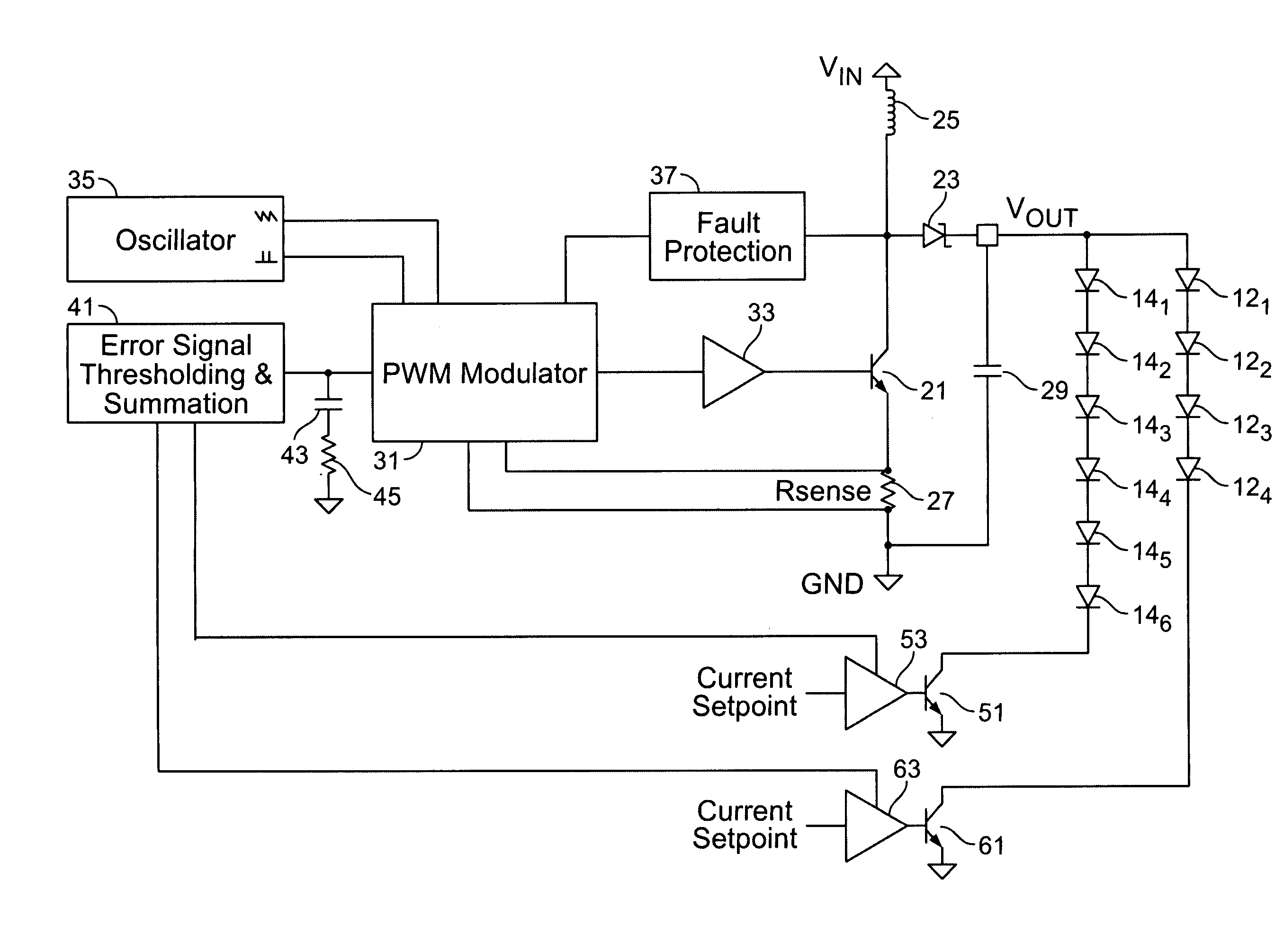
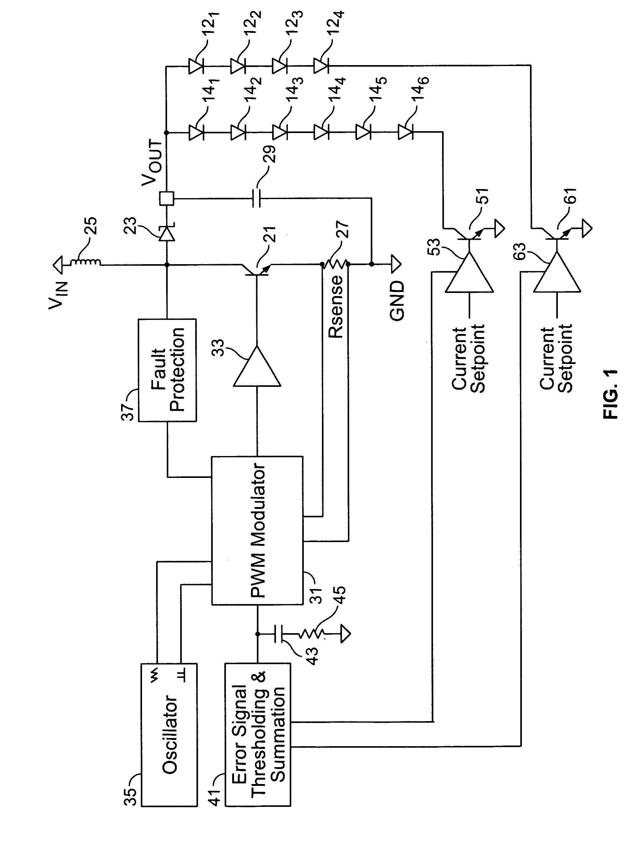
[0021]The invention provides a power supply for efficiently driving plural LED strands in which multiple current regulators feed back control information to a single voltage regulator or converter, allowing the power supply to adjust the output voltage to the optimum setpoint for varying load conditions.

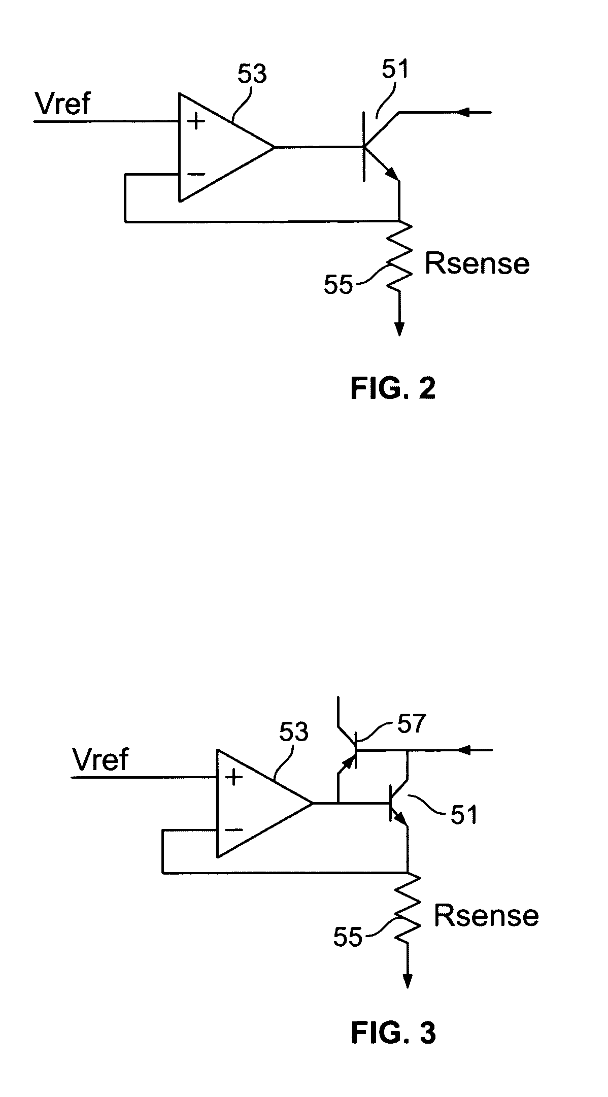
[0022]More particularly, the power supply provides directly regulated multiple load currents with an indirectly regulated single output voltage. Linear current regulators independently regulate the load currents, and the output voltage of the voltage regulator or converter is adjusted using feedback information from all current regulators. This allows very accurate current regulation under changing output voltage conditions, as well as the ability to switch between several operating conditions as different loads are energized or de-energized. Moreover, the voltage regulator or converter does not need a pre-determined output voltage setpoint and always seeks the lowest possible output...


PUM


Abstract

A power supply for plural loads coupled in parallel comprises a voltage regulator, a plurality of current regulators, and an error control circuit. The voltage regulator provides a common output voltage to the plural loads. The voltage regulator comprises a sensor circuit providing a voltage sense signal corresponding to the output voltage, which provides feedback to regulate the output voltage at a selected level. The plurality of current regulators are coupled to respective ones of the plural loads. Each of the plurality of current regulators regulates current drawn by respective ones of the plural loads to within a desired regulation range. The plurality of current regulators each further provide a respective error signal corresponding to an ability to remain within the desired regulation range. The error control circuit is operatively coupled to the voltage regulator and to the plurality of current regulators. The error control circuit receives the error signals from the plurality of current regulators and provides a common error signal to the voltage regulator. The voltage regulator thereby changes the selected level of the output voltage in response to the common error signal. Accordingly, the selected level of the output voltage remains at a minimum voltage necessary to keep the plural loads in the desired regulation range.

Description

RELATED APPLICATION DATA[0001]This application claims priority pursuant to 35 U.S.C. § 119(e) to provisional patent application Ser. No. 60 / 741,156, filed Nov. 30, 2005, the subject matter of which is incorporated by reference herein in its entirety.BACKGROUND OF THE INVENTION[0002]1. Field of the Invention[0003]The present invention relates to driver circuits for light emitting diodes (LEDs).[0004]2. Description of Related Art[0005]LEDs are increasingly used in lighting applications, such as to provide back lighting for a liquid crystal display in which the LEDs are generally connected together in series in long strands. In such applications, it is desirable that the LEDs provide generally uniform illumination. Accordingly, it is necessary to closely regulate the current applied to the LED strands in order to maintain uniform illumination and provide efficient operation.[0006]There are two methods generally used in the art to achieve constant current regulation of loads such as ser...

Claims


Application Information

Patent Timeline
04 Sep 2007
Publication
US7265504B2
IPC
G05F1/00
CPC
H05B33/0827; H05B33/0851; H05B45/3725; H05B45/46; H05B45/52
Inventors
GRANT, MATTHEW ALAN