Base station apparatus and communication terminal apparatus

a technology of communication terminals and base stations, applied in the direction of channel coding adaptation, polarisation/directional diversity, wireless communication, etc., can solve the problems of reducing the efficiency of radio frequency band, the communication terminal apparatus cannot help but receive packet data with much inferior quality, and the measurement of reception quality may not reflect when packet data is actually transmitted with directivity. , to achieve the effect of maximizing the utilization efficiency of communication paths, high efficiency and high quality

Active Publication Date: 2007-09-04
GK BRIDGE 1
View PDF12 Cites 6 Cited by
  • Summary
  • Abstract
  • Description
  • Claims
  • Application Information

AI Technical Summary

Benefits of technology

[0007]It is an object of the present invention to provide a base station apparatus and communication terminal apparatus capable of receiving packet data with high quality, providing high efficiency for a radio frequency band and maximizing communication path utilization efficiency.

Problems solved by technology

However, in the case of a conventional base station apparatus and communication terminal apparatus, it may be necessary to often change directivity control when communication terminal apparatuses exist over a wide range of area and there may exist a time difference in transmission timing between a reference signal and packet data, with the result that although adaptive modulation, etc., is performed based on reception quality measured using the reference signal, the measured reception quality may not be reflected when packet data is actually transmitted with directivity.
In this case, even if the modulation multi-valued number and coding rate, etc., are optimized and packet data is transmitted, there may be a situation in which the communication terminal apparatus cannot help but receive the packet data with quality much inferior to the expected quality, being unable to demodulate the packet data or there may also be a situation in which the quality becomes by far better than the expected quality, causing the efficiency of the radio frequency band to decrease, and even if the adaptive array antenna technology is introduced to the system carrying out adaptive modulation, it is not possible to make the most of advantages of both adaptive modulation and adaptive array antenna technology or maximize communication path utilization efficiency.

Method used


Image

  • Base station apparatus and communication terminal apparatus
  • Base station apparatus and communication terminal apparatus
  • Base station apparatus and communication terminal apparatus

Examples


embodiment 1

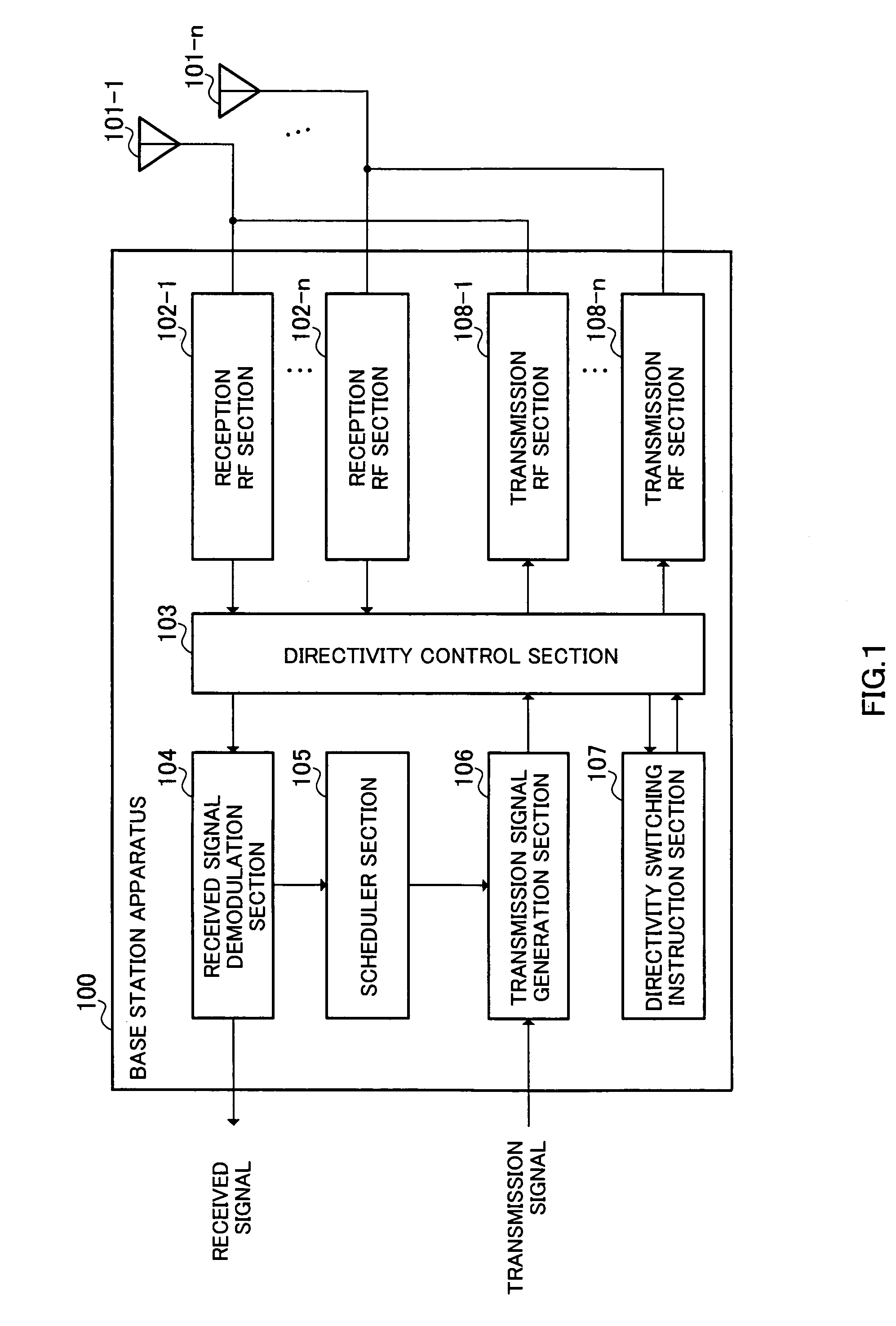
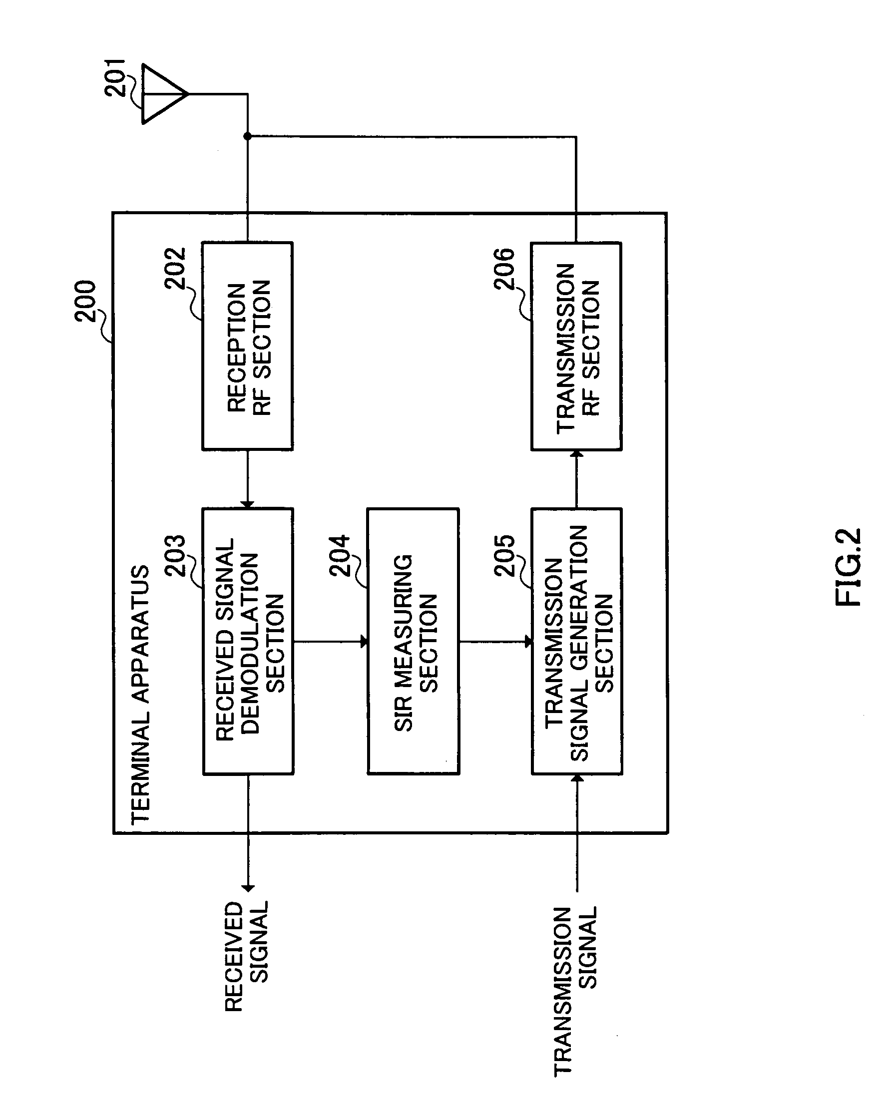
[0025]FIG. 1 illustrates the configuration of a base station apparatus according to Embodiment 1 of the present invention, FIG. 2 illustrates the configuration of a communication terminal apparatus according to Embodiment 1 of the present invention and FIG. 3 illustrates the configuration of a directivity switching instruction section according to Embodiment 1 of the present invention.

[0026]The base station apparatus 100 is mainly constructed of antenna elements 101-1 to 101-n, reception RF sections 102-1 to 102-n, a directivity control section 103, a received signal demodulation section 104, a scheduler section 105, a transmission signal generation section 106, a directivity switching instruction section107 and transmission RF sections 108-1 to 108-n.

[0027]Furthermore, the terminal apparatus 200 is mainly constructed of an antenna element 201, a reception RF section 202, a received signal demodulation section 203, an SIR measuring section 204, a transmission signal generation secti...

embodiment 2

[0051]FIG. 6 illustrates the configuration of a base station apparatus according to Embodiment 2 of the present invention, FIG. 7 illustrates the configuration of a communication terminal apparatus according to Embodiment 2 of the present invention and FIG. 8 illustrates the configuration of a directivity switching instruction section according to Embodiment 2 of the present invention. This embodiment is characterized in that a base station apparatus notifies a terminal of a timing for switching between directivities. This embodiment differs in FIG. 6 from the embodiment in FIG. 1 in the configuration that a directivity switching signal generation section 601 is provided and differs in FIG. 7 from the embodiment in FIG. 2 in the configuration that a directivity switching decision section 701 is provided. The same components as those in FIG. 1 and FIG. 2 are assigned the same reference numerals and explanations thereof will be omitted.

[0052]A transmission signal generation section 10...

embodiment 3

[0065]FIG. 11 illustrates the configuration of a base station apparatus according to Embodiment 3 of the present invention, FIG. 12 illustrates the configuration of a terminal apparatus which is a communication terminal apparatus according to Embodiment 3 of the present invention, FIG. 13 illustrates the configuration of a directivity switching instruction section 1103 according to Embodiment 3 of the present invention and FIG. 14 illustrates the configuration of a directivity number information decision section according to Embodiment 3 of the present invention. This embodiment is characterized in that a base station apparatus notifies a terminal of directivity switching timings and directivity number information. This embodiment differs in FIG. 11 from the embodiment in FIG. 1 in that a directivity switching signal generation section 1101 and a directivity number information generation section 1102 are provided and differs in FIG. 12 from the embodiment in FIG. 2 in that a directi...


PUM


Abstract

A reception quality reporting system may include a communication terminal that measures reception directivity quality in a quality decision signal received from a base station apparatus. The communication terminal decides a switching timing at which directivities of packet data are switched based on directivity switching timing information communicated by the base station and nullifies the reception quality measured in a period before the switching timing. The communication terminal transmits to the base station apparatus reception quality information indicating the measured reception quality.

Description

TECHNICAL FIELD[0001]The present invention relates to a base station apparatus and communication terminal apparatus, and more particularly, to a base station apparatus and communication terminal apparatus that transmit / receive packet data modulated and coded according to channel quality.BACKGROUND ART[0002]Conventionally, there is a scheme for a base station to use an adaptive array antenna and improve transmission quality through transmission with directivity.[0003]On the other hand, there is also a scheme called “adaptive modulation” in mobile communications under which a modulation / demodulation scheme is adaptively switched according to fluctuations in reception quality caused by fading. Setting an optimum modulation scheme according to a communication environment allows a large volume of packet data to be transmitted at high speed.[0004]When introducing a technology of an adaptive array antenna to a system carrying out adaptive modulation, a communication terminal apparatus meas...

Claims


Application Information

Patent Timeline
Patent Type & Authority Patents(United States)
IPC IPC(8): H04B1/00H04B15/00H04B7/08H04B7/10H04B7/26H04L1/00H04W16/28
CPCH04B7/0604H04B7/0695H04L1/0003H04L1/0009H04W16/28
Inventor HOSHINO, MASAYUKIMIYOSHI, KENICHI
Owner GK BRIDGE 1
Why Eureka
Try Eureka