Single integrated humidity and ventilation control in an HVAC system

a humidity control and hvac technology, applied in the field of indoor central heating, ventilation and air conditioning (hvac) systems, can solve the problems of air inside the building structure that has a tendency to become wet or humid, low indoor relative humidity, and dry air inside the building structure, so as to avoid avoid condensation, and prevent condensation on the interior surface

Active Publication Date: 2007-09-11
CARRIER CORP
View PDF4 Cites 80 Cited by
  • Summary
  • Abstract
  • Description
  • Claims
  • Application Information

AI Technical Summary

Benefits of technology

[0016]In another disclosed embodiment, the single integrated central control includes, at the user's option, a protection feature for avoiding condensation on the interior surfaces of a building, as disclosed in the commonly assigned, co-pending application entitled “Determination of Maximum Allowable Humidity in Indoor Space to Avoid Condensation Inside Building Envelope,” U.S. patent application Ser. No. 11 / 016,373 filed on Dec. 17, 2004, the disclosure of which is incorporated in its entirety herein by reference. This option provides automatic adjustment of the desired indoor relative humidity to prevent condensation on the interior surfaces of the building based on actual indoor and outdoor characteristics.

Problems solved by technology

In the heating season, i.e. when the outdoor temperature drops below the user desired indoor temperature, the air inside a building structure has a tendency to become dry, i.e. the indoor relative humidity is low.
In the cooling season, i.e. when the outdoor temperature exceeds the user desired indoor temperature, the air inside the building structure has a tendency to become wet or humid, i.e. the indoor relative humidity is high.

Method used


Image

  • Single integrated humidity and ventilation control in an HVAC system
  • Single integrated humidity and ventilation control in an HVAC system
  • Single integrated humidity and ventilation control in an HVAC system

Examples


Embodiment Construction

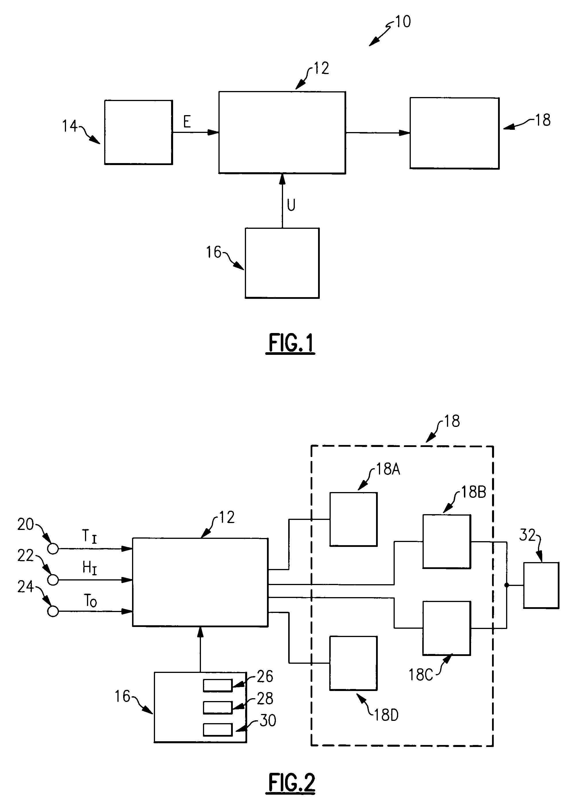
[0029]A schematic view of a building HVAC system 10 is illustrated in FIG. 1. A single integrated central control unit 12 is operable to manipulate a multiple of indoor environmental characteristics based upon actual environmental characteristics E sensed by at least one environmental sensor 14 and user input U entered by a user into a user interface 16. The single integrated central control unit 12 manipulates the indoor environmental characteristics by selectively activating and / or deactivating at least one device 18.

[0030]A detailed schematic view of a building HVAC system including a single integrated central control unit 12 is illustrated in FIG. 2. The single integrated central control unit 12 receives actual environmental input from a plurality of sensors. An indoor temperature sensor 20, an indoor relative humidity sensor 22, and an outdoor temperature sensor 24 are operable to transmit an actual indoor temperature input (TI), an indoor relative humidity input (HI), and an a...


PUM

PropertyMeasurementUnit
temperatureaaaaaaaaaa
relative humidityaaaaaaaaaa
relative cooling humidityaaaaaaaaaa

Abstract

HVAC systems are employed to control the indoor environmental characteristics of a building structure to make it comfortable for its inhabitants. An HVAC system includes one single integrated central control to regulate an indoor temperature level, an indoor relative humidity level and an indoor fresh air level of a building structure during both a heating season and a cooling season. Further, the single integrated central control is operable to selectively activate / deactivate an indoor blower to control a sensible ratio within a building structure. In addition, a protection feature for avoiding condensation on the interior surfaces of the building structure is included as an user selectable option.

Description

[0001]The application claims priority to U.S. Provisional Application No. 60 / 537,528 which was filed on Jan. 20, 2004, the disclosure of which is incorporated in its entirety herein by reference.BACKGROUND OF THE INVENTION[0002]This application relates to an indoor central heating, ventilation, and air conditioning (HVAC) system wherein control of an indoor temperature level, an indoor relative humidity level, and an indoor fresh air level are combined into one single integrated central control that is operable to manage an indoor environment during both a heating season and a cooling season.[0003]HVAC systems are employed to control the indoor environmental characteristics of a building structure to make it comfortable for its inhabitants. A typical HVAC system includes a temperature control device or thermostat and one or more humidity control devices known as humidistats.[0004]A thermostat is employed as a control device to regulate the indoor temperature level. Thermostats sense...

Claims


Application Information

Patent Timeline
Patent Type & Authority Patents(United States)
IPC IPC(8): F25B29/00F25B49/00F25D17/04B01F23/10F24F11/00
CPCF24F11/0008F24F11/001G05D22/02G05D23/1931F24F11/0012F24F11/0015F24F2011/0013F24F11/30F24F2110/00F24F2110/10F24F2110/12F24F2110/20F24F11/52F24F11/67F24F11/54F24F2221/50
Inventor SHAH, RAJENDRA K.
Owner CARRIER CORP
Why Eureka
Try Eureka