
Method and system for providing cruciform steered, bent biconic and plasma suppression for maximum accuracy

a technology of biconic and plasma suppression, applied in the field of plasma induced communication disruption reduction methods and systems, can solve the problems of communication disruption, communication disruption during reentry affecting reentry vehicles, communication disruption during reentry, etc., and achieve the effect of reducing plasma induced communication disruption, reducing the electron density in the plasma, and reducing the disruption of plasma communication

Inactive Publication Date: 2007-09-11
LOCKHEED MARTIN CORP
View PDF42 Cites 6 Cited by
  • Summary
  • Abstract
  • Description
  • Claims
  • Application Information

AI Technical Summary

Benefits of technology

The solution effectively reduces or eliminates plasma-induced communication blackouts, enabling continuous GPS communication and improving targeting accuracy by maintaining electron density low enough to prevent signal attenuation, thus enhancing vehicle control and navigation during reentry.

Problems solved by technology

One result of plasma formation around a reentry vehicle is communication disruption during reentry.
The free electrons racing around in the plasma interfere with the electromagnetic waves used for radio communication (the RF signals), resulting in communication disruption.
Communication disruption during reentry affects reentry vehicles in many ways.
For example; the plasma effect adversely affects the performance of reentry vehicles with missile launch capability.
However, the plasma effect disrupts the vehicles' communication with the GPS satellites, causing so-called GPS blackouts during reentry.
Because the reentry vehicles cannot be guided by GPS during the critical reentry phase, performance is negatively affected by the plasma induced communication disruption.

Method used


Image

  • Method and system for providing cruciform steered, bent biconic and plasma suppression for maximum accuracy
  • Method and system for providing cruciform steered, bent biconic and plasma suppression for maximum accuracy
  • Method and system for providing cruciform steered, bent biconic and plasma suppression for maximum accuracy

Examples


Embodiment Construction

[0040]One or more embodiments of the present invention will now be described. When a space-borne object enters atmosphere from space, the object is traveling at a very high speed due to the pull of gravity—i.e., the gravitational acceleration. Since space is basically vacuum, there is no resistance or friction from air until the object hits the upper layers of atmosphere, and the falling object typically reaches a speed many times the speed of sound by the time it encounters outer atmosphere. An object traveling at a hypersonic speed in atmosphere creates a large shockwave, especially in the wake of the object's flight path, producing intense pressures and heat.

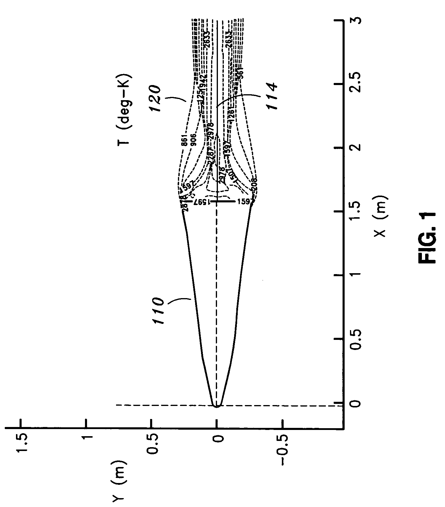
[0041]FIG. 1 illustrates temperature distribution in the wake of a reentry vehicle during reentry into atmosphere. As shown in FIG. 1, the reentry vehicle 110 is subject to intense heat and pressures during reentry into atmosphere, reaching a temperature of 3,000 degree Kelvin or higher in the wake of the reentry vehicle. In ...


PUM


Abstract

A system for reducing plasma induced communication disruption is disclosed. The system utilizes an electrophilic gas injectant, bent reentry vehicle nose shaping and a number of flaps configured to provide 3-axis steering capability. Injecting electrophilic gas injectant into plasma accomplishes reduction of plasma induced communication disruption by removing free electrons in the plasma which causes the communication disruption. For reentry vehicles, a bent biconic nose also reduces plasma effect during reentry. By combining electrophilic gas injection and bent nose shaping, the system reduces and / or eliminates plasma induced communication disruption, such as, GPS communication blackout, for a reentry vehicle during reentry. Furthermore, the 3-axis steering capability renders the reentry vehicle more maneuverable. Performance of the reentry vehicle during reentry, such as, target accuracy, is thus improved.

Description

CROSS-REFERENCE(S) TO RELATED APPLICATION(S)[0001]The present application is a continuation-in-part application of co-pending U.S. patent application Ser. No. 10 / 849,268, entitled “SYSTEM AND METHOD FOR REDUCING PLASMA INDUCED COMMUNICATION DISRUPTION UTILIZING ELECTROPHILIC INJECTANT AND SHARP REENTRY VEHICLE NOSE SHAPING”, filed on May 18, 2004, the disclosure of which is hereby incorporated by reference in its entirety for all purposes.STATEMENT AS TO RIGHTS TO INVENTIONS MADE UNDER FEDERALLY SPONSORED RESEARCH OR DEVELOPMENT[0002]Not Applicable.BACKGROUND OF THE INVENTION[0003]The present invention generally relates to methods and systems for reducing plasma induced communication disruption, and in particular to methods and systems for reducing plasma induced communication disruption utilizing electrophilic injectant and sharp reentry vehicle nose shaping.[0004]Blazing fiery descent of space-borne objects into the Earth atmosphere is a well known phenomenon. To avoid damage or d...

Claims


Application Information

Patent Timeline
Patent Type & Authority Patents(United States)
IPC IPC(8): B64G1/00
CPCB64G1/62
Inventor TETER, ROGER D.DUNN, STEVEN A.MEYER, J. WILLIAM
Owner LOCKHEED MARTIN CORP
Learn More