Spade drill bit

a drill bit and pad technology, applied in the field of drill bits, can solve the problems of frequent high localized temperature, high wear rate, and blowout of wood on the backside, and achieve the effects of reducing drill vibration, easy clearing, and energy-saving drill bits

Inactive Publication Date: 2007-09-11
CREDO TECH CORP
View PDF6 Cites 38 Cited by
  • Summary
  • Abstract
  • Description
  • Claims
  • Application Information

AI Technical Summary

Benefits of technology

[0014]It is therefore an objective of the present invention to provide an energy efficient drill bit. It is a further object of the invention to provide a drill bit design in which chips are more easily cleared out of the hole being drilled. It is yet a further object of the invention to provide a drill bit design which reduces drill vibrations and results in better quality holes.
[0015]It is yet a further object of the invention to provide a drill bit having a lower wear rate and which, during drilling, avoids excessively high localized temperatures. It is yet a further object of the invention to provide a drill bit which exits a piece of wood without grabbing the work piece as it exits the hole.

Problems solved by technology

Grabbing may result in a wood blowout and splintering on the backside because the last portion of the uncut material 31 is pushed out rather than cut.
Another problem associated with this type of prior spade drill bit is that the spurs 26, 28 frequently experience high localized temperatures and high wear rates.

Method used


Image

  • Spade drill bit
  • Spade drill bit
  • Spade drill bit

Examples


Embodiment Construction

[0030]Reference will now be made in detail to various presently preferred embodiments of the invention, examples of which are illustrated in the accompanying drawings. In the various FIGS. some of the structures are referenced with similar reference numerals.

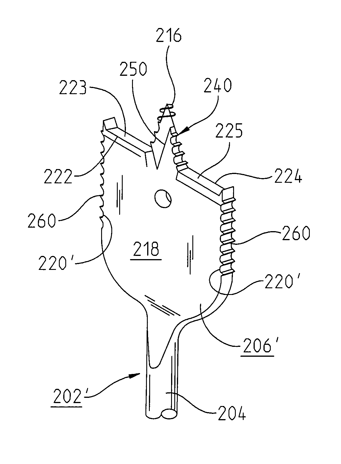
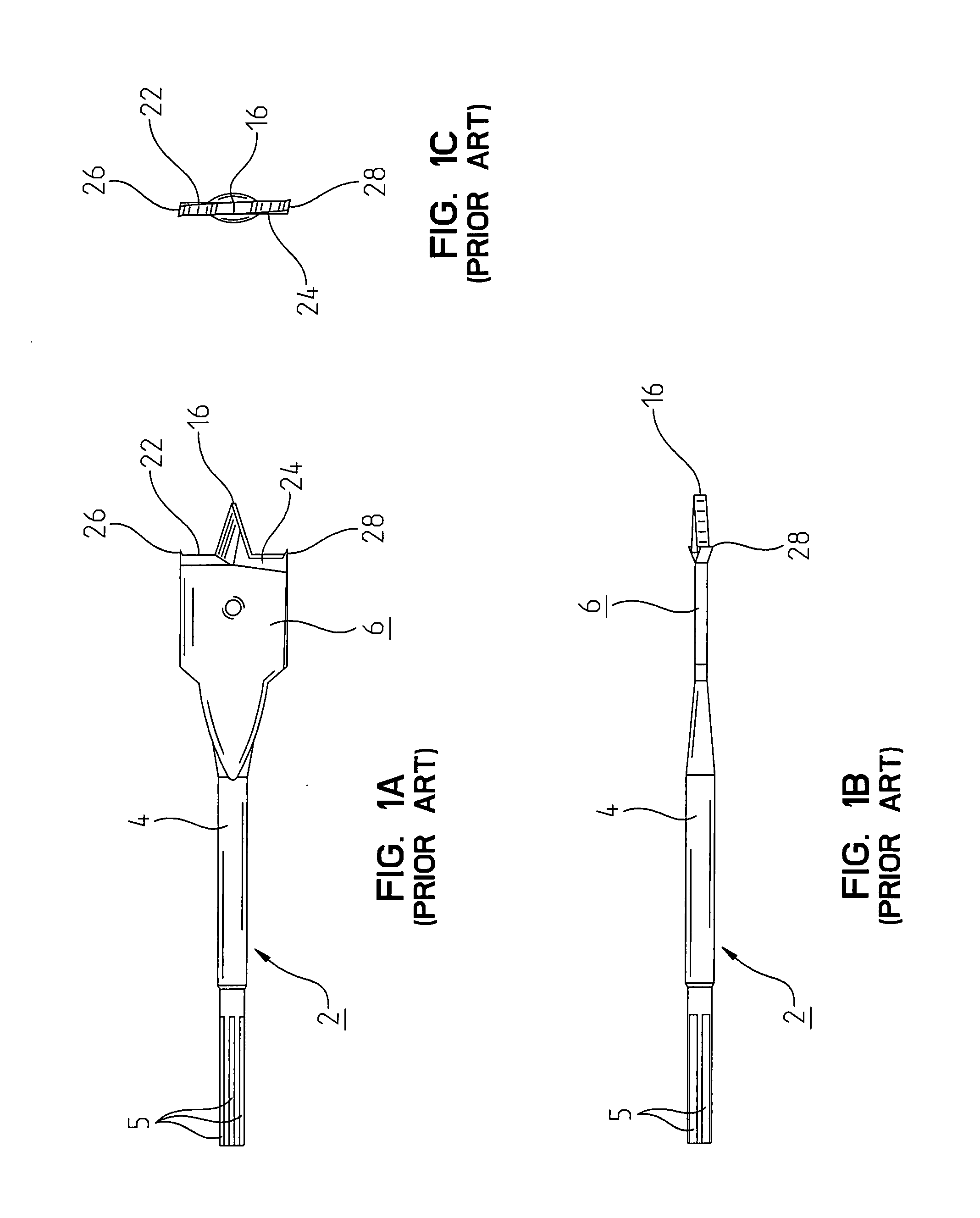
[0031]Referring to FIG. 6, one embodiment of the invention is depicted in which a spade-type drill bit 202 includes a shaft 204 terminating in a driving end 205. A cutting head 206 is formed at the opposite end of the shaft. These components of the drill bit 202 can be similar to the like components of the bits 2 and 102 in FIGS. 1A-c and 3A-C, respectively. In other words, the driving end 204 can have a hex configuration to mate with a drill chick and the head 206 can have a flat, spade profile. The head 206 includes a center point 216 and cutting edges 222 and 224, like both prior drill bits described above. Moreover, the head 206 of the present embodiment can include spurs 226 and 228, similar to the spurs 26 and 28 of the bi...


PUM

PropertyMeasurementUnit
axial rake angleaaaaaaaaaa
depthaaaaaaaaaa
included angleaaaaaaaaaa

Abstract

A spade drill bit (202) comprises a shaft (204) having one end (205) configured to be engaged to a driving tool and a cutting head (206) attached at an opposite end of said shaft (204). The cutting head (206) includes a center point (216) having threads (240) defined thereon, including continuous threads (247) adjacent the tip and discontinuous threads (242) thereafter toward the base.

Description

FIELD OF THE INVENTION [0001]The present invention relates to a drill bit. More specifically, the present invention relates to a spade-type drill bit.BACKGROUND OF THE INVENTION [0002]One conventional spade-type drill bit is depicted in FIGS. 1A-C. The bit 2 has a cutting head 6 situated at the end of an elongated shaft 4. The opposite end of the shaft 4 is preferably provided with hexagonal flats 5 for engagement within a conventional drill chuck. As best in FIG. 1B, the head 6 is substantially flat and is provided with cutting edges 22 and 24. A central point 16 is provided along the longitudinal axis of the bit 2. The outer periphery of the bit is provided with cutting spurs 26, 28.[0003]In use, the point 16 of the rotating bit 2 penetrates the workpiece first and serves as a centering guide for the bit. As the bit is advances further into the workpiece, the spurs begin cutting into the material. Finally, as the bit is advanced further, the cutting edges 22, 24 begin to shave thi...

Claims


Application Information

Patent Timeline
Patent Type & Authority Patents(United States)
IPC IPC(8): B27G15/00
CPCB27G15/00Y10T408/909Y10T408/902Y10T408/9065
Inventor WIKER, JUERGENPHILLIPS, GREGORY A.
Owner CREDO TECH CORP
Why Eureka
Try Eureka