Mounting substrate and driving device using same

a technology of mounting substrate and driving device, which is applied in the direction of electrical apparatus construction details, non-enclosed substations, substations, etc., can solve the problems of affecting productivity, affecting the overall structure of the substrate, and becoming difficult to fit within the limited space allowable in the vehicle, so as to achieve the effect of dissipating hea

Inactive Publication Date: 2007-09-11
OMRON AUTOMOTIVE ELECTRONICS CO LTD
View PDF14 Cites 23 Cited by
  • Summary
  • Abstract
  • Description
  • Claims
  • Application Information

AI Technical Summary

Benefits of technology

[0010]It is therefore an object of this invention to provide a mounting substrate capable of effectively dissipating heat without increasing the number of constituent components, as well as a driving device making use of such a mounting substrate.
[0013]Because the mounting substrate according to this invention is provided with a metallic heat dissipating plate having a heat dissipating part that is not covered with any insulating material but is exposed externally, heat generated by highly heat-generating components can be more efficiently dissipated. Moreover, since this heat dissipating plate is provided by using the same material as and as a part of the same circuit pattern of the base plate part, it can be produced easily and hence inexpensively, say, by punching out of a hoop material.
[0014]According to a preferred embodiment of the invention, at least one of the legs and the heat dissipating plate are disposed next to each other on the same end side of the base plate part. This means that, when they are formed together from the material for the base plate part, the portion that would otherwise be cut off and discarded is bent and made into the heat dissipating part of the mounting substrate. In other words, the portion that would be wasted is reduced and hence the production cost is reduced according to this preferred embodiment.
[0015]The heat dissipating plate according to the preferred embodiment of the invention is further provided with a heat-receiving part disposed inside the base plate part and the highly heat-generating circuit components are mounted proximally to the heat dissipating part and to the heat-receiving part either directly or through a thinned portion of the insulating material such that the heat can be dissipated efficiently.

Problems solved by technology

Problems occur with such driving devices with a control capability as described above if the circuit components for the PWM control such as the switching element are simply mounted to the same substrate with the other basic circuit components such as the relays and the switches as described above.
In other words, as the device becomes larger in the direction parallel to the substrate, it becomes difficult to fit within a limited space allowable in a vehicle.
In the case of a driving device not adapted to carry out the PWM control, furthermore, the structure of the substrate as a whole becomes different and hence the productivity is adversely affected.
With a structure having all of the aforementioned circuit components mounted to an inexpensive printed circuit board of a general kind, heat generated by the circuit components for the PWM control such as the switching element described above cannot be dissipated effectively to the exterior and it is not possible to prevent the overheating of the switching element or other circuits around it.
There are problems, however, to actually produce such a structure.
For example, although the heat generated by the circuit components for the PWM control such as switching element must be eliminated efficiently, a simple structure as disclosed in aforementioned Japanese Patent Publication Tokkai 10-201050 is not sufficient.
If a heat-radiating plate is additionally provided as disclosed in aforementioned Japanese Patent Publication Tokkai 8-11732, on the other hand, the total number of components becomes large and this affects the production cost adversely.
If the structure is such that another substrate is mounted onto a main substrate, another problem arises regarding the connection between the switch on the main substrate and the operation section by avoiding interferences among the components.
In the example of aforementioned Japanese Patent Publication Tokkai 10-201050, it would be difficult to avoid interferences between the connecting part for the switch and the operating knob and another substrate unless the main substrate is made larger in the lateral direction.

Method used


Image

  • Mounting substrate and driving device using same
  • Mounting substrate and driving device using same
  • Mounting substrate and driving device using same

Examples


Embodiment Construction

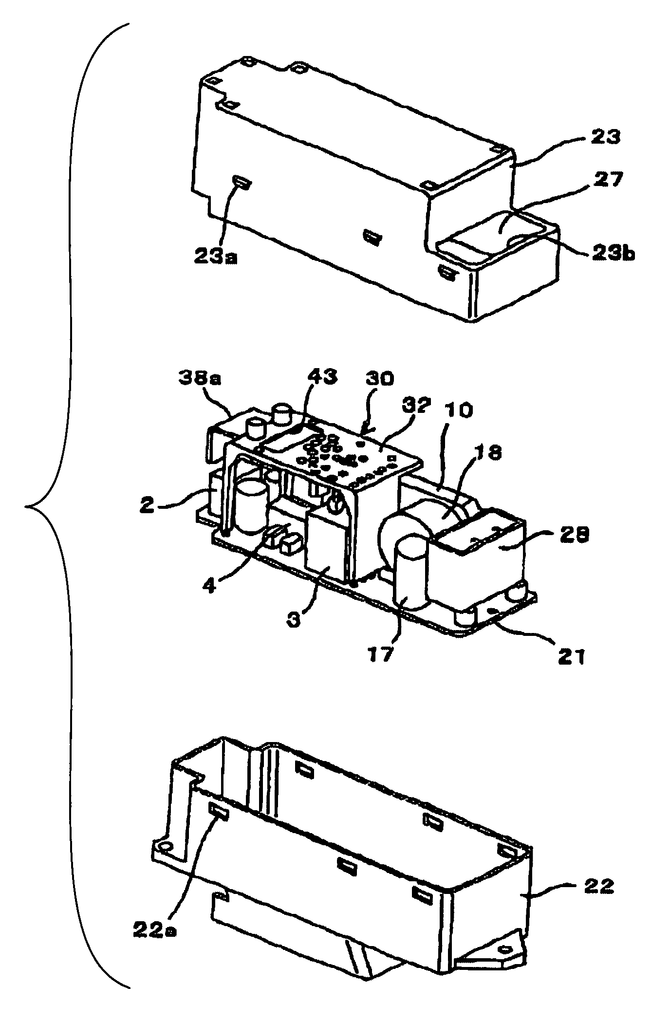
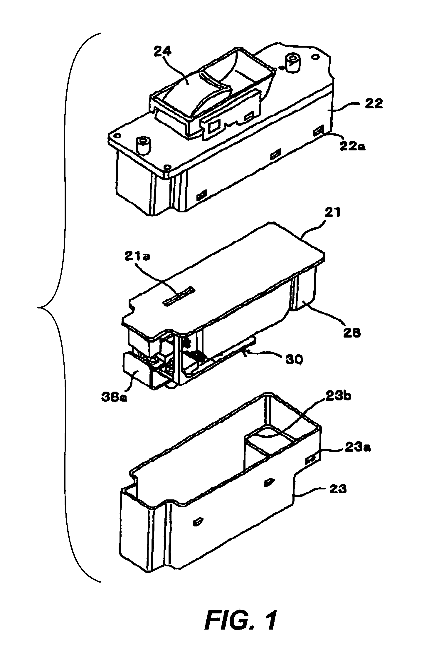
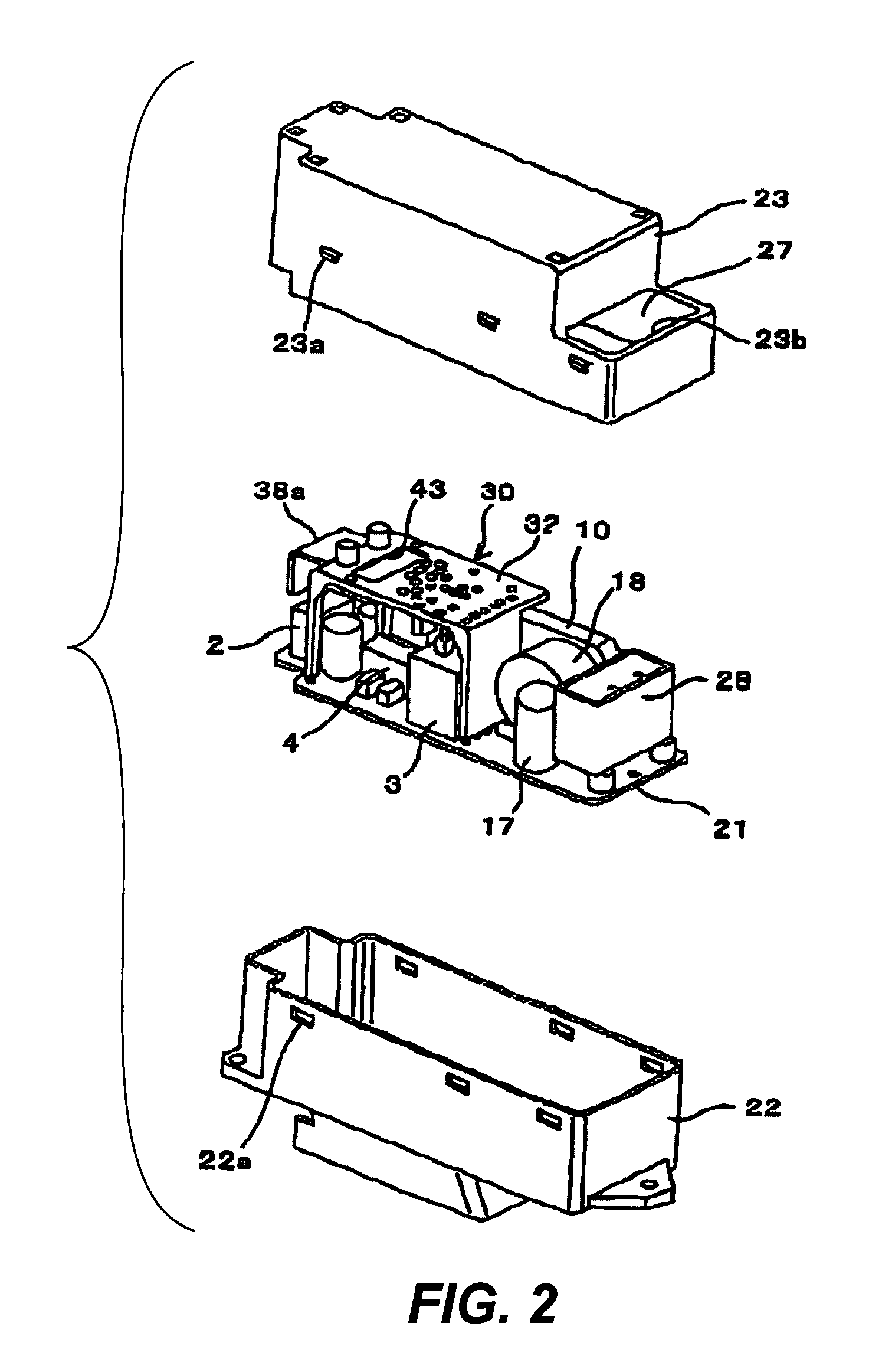
[0027]The invention will be described next by way of an embodiment with reference to the figures. FIG. 1 is an exploded diagonal view of a driving device embodying this invention, which is a driving unit for a power window of a vehicle next to a passenger seat, showing the side of its front surface. FIG. 2 is its exploded diagonal view, showing the side of its back surface. FIG. 3A is a diagonal view of the mounting substrate (with components mounted) and FIG. 3B is a diagonal view of the base substrate (with components mounted). FIG. 4 is a circuit diagram for showing main circuits of the driving device. FIGS. 5-8 are drawings for explaining the production process of the mounting substrate. FIGS. 9A, 9B and 9C are diagonal views of other mounting substrates embodying this invention.

[0028]With reference to FIG. 4 and other figures, the main circuit for the driving device includes relays 2 and 3 which serve to supply power to a motor 1, say, for opening and closing a window of a vehi...


PUM


Abstract

A driving device for a motor has a mounting substrate mounted to a base substrate. Highly heat-generating components such as a switching element for PWM control are mounted to the mounting substrate and only less heat-generating circuit components are mounted to the base substrate. The mounting substrate has a base plate part made of a metallic plate material surround by a molded insulating material but includes a heat dissipating part where the insulating material is removed and the internal metallic plate material is exposed.

Description

[0001]Priority is claimed on Japanese Patent Application 2004-199264 filed Jul. 6, 2004.BACKGROUND OF THE INVENTION[0002]This invention relates to a mounting substrate suitable, for example, for a power window system for a vehicle as well as to a driving device using such a substrate.[0003]Electronic controls are the main method of control for the likes of a power window of a vehicle, say, for automatically reversing the direction of motion of a window when an inserted object is detected. Thus, a common driving method is to make use of a relay, as disclosed in Japanese Patent Publication Tokkai 10-169311, in a driving device that supplies power appropriately to a motor serving as the power source for such an opening and closing mechanism and is provided with a control circuit including a control means such as a microcomputer. Explained more in detail, such a driving device is comprised of two relays for supplying power to the motor so as to rotate is in a positive direction (say, fo...

Claims


Application Information

Patent Timeline
Patent Type & Authority Patents(United States)
IPC IPC(8): H05K7/20
CPCH05K1/0203H05K1/141H05K7/20909H05K3/202H05K3/4092H05K2201/09118
Inventor HIRATA, AKIHIKOSUGIURA, TOKIHIKOTANAKA, YASUHIDE
Owner OMRON AUTOMOTIVE ELECTRONICS CO LTD
Why Eureka
Try Eureka