Method for mutual monitoring of components of a distributed computer system

a computer system and component technology, applied in the direction of program control, total factory control, instruments, etc., can solve the problems of relative great complexity in hardware and software to meet the high reliability requirements, and it is not easy to simply lower the safety requirements. , to achieve the effect of reducing complexity

Inactive Publication Date: 2007-09-11
ROBERT BOSCH GMBH
View PDF20 Cites 27 Cited by
  • Summary
  • Abstract
  • Description
  • Claims
  • Application Information

AI Technical Summary

Benefits of technology

[0011]One object of the present invention is to be able to implement monitoring of components of a distributed computer system for a safety-relevant application using a lower complexity while retaining existing safety requirements.
[0018]It is to be expected that in the future there will be a drastic increase in the number of distributed computer systems for safety-relevant applications, in particular in motor vehicles. For this reason, the present invention may be particularly relevant, because through the present invention, it is possible to meet high safety requirements for distributed computer systems with markedly reduced complexity and without any sacrifice of safety. Therefore, it is possible to save on costs in the design and production of such computer systems while on the other hand it is possible to implement the monitoring sequences for monitoring fault-free operation of the components of the computer system much more simply and thus also more transparently—which is even more important with the safety-relevant applications in question here. Therefore, it is possible to simplify the design and implementation of the monitoring functions of components of a distributed computer system while also greatly reducing the susceptibility of the monitoring method to faults because of a faulty design or a faulty implementation.
[0021]According to another preferred embodiment of the present invention, the mutual monitoring functions use model calculations to check on the results determined by the components. Typical examples of a model calculation on the example of an electronic brake system include a simple calculation of wheel slip on the basis of rotational speed signals, calculation of the reference speed from rotational speed signals or calculation of a braking force distribution from existing signals.

Problems solved by technology

It has proven to be a disadvantage of the conventional computer systems and the conventional method of mutual monitoring of components of the computer systems that a relatively great complexity is required in terms of hardware and software to meet the high reliability requirements.
On the other hand, for understandable reasons, it is not readily possible to simply lower the safety requirements in the case of safety-relevant applications.

Method used


Image

  • Method for mutual monitoring of components of a distributed computer system
  • Method for mutual monitoring of components of a distributed computer system
  • Method for mutual monitoring of components of a distributed computer system

Examples


Embodiment Construction

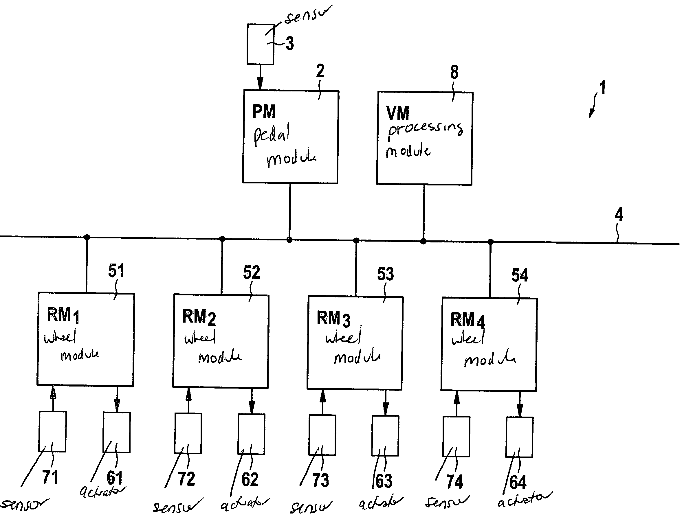
[0037]The present invention relates to a method of mutual monitoring of the components of a distributed computer system. This mutual monitoring may be important in the case of safety-relevant applications in particular, i.e., in systems in which fault-free output of at least one variable is required. A typical application is for electric brake systems in motor vehicles (brake-by-wire). The following discussion is based on an electric brake system using a distributed computer system. However, the present invention is not limited to such electric brake systems.

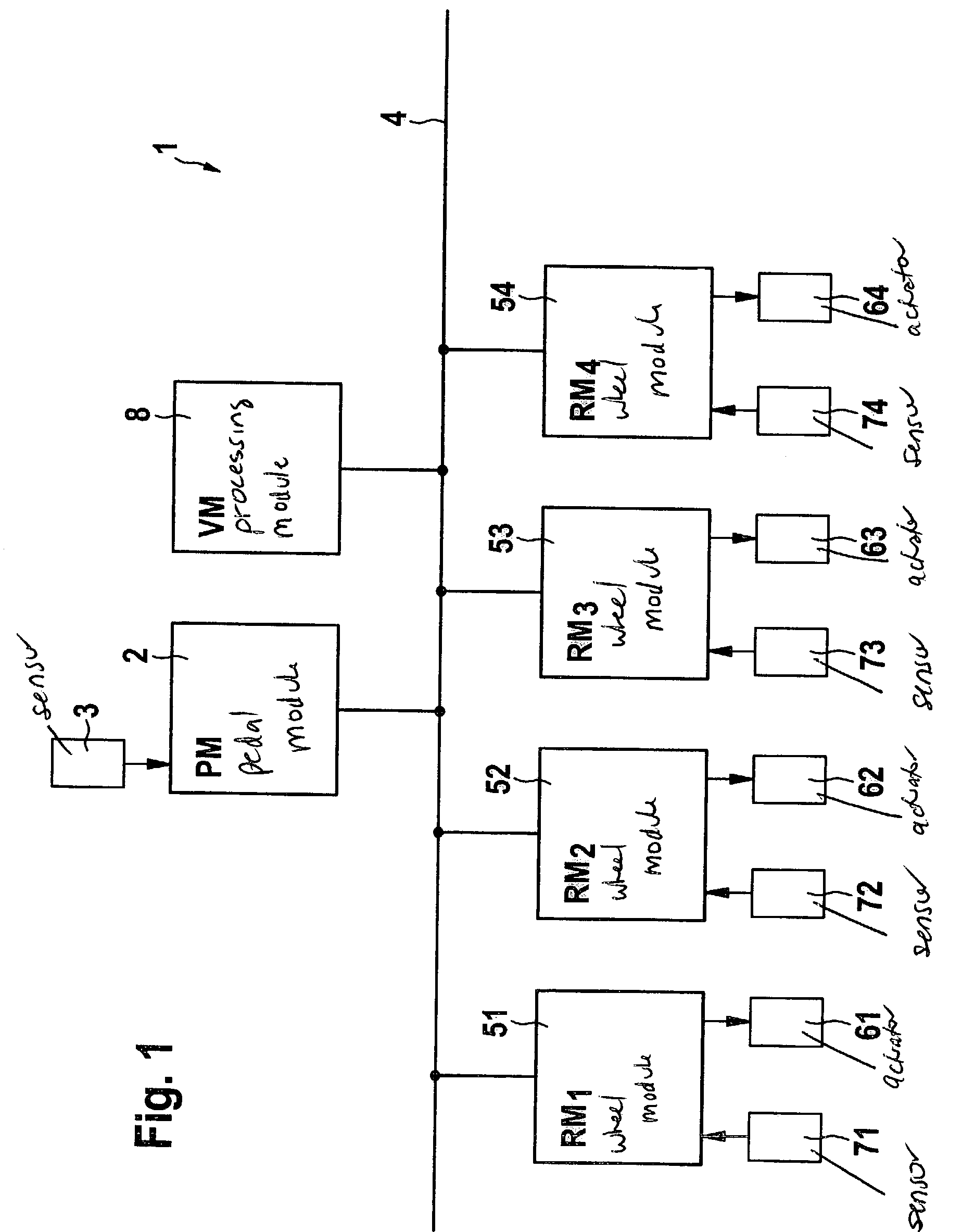
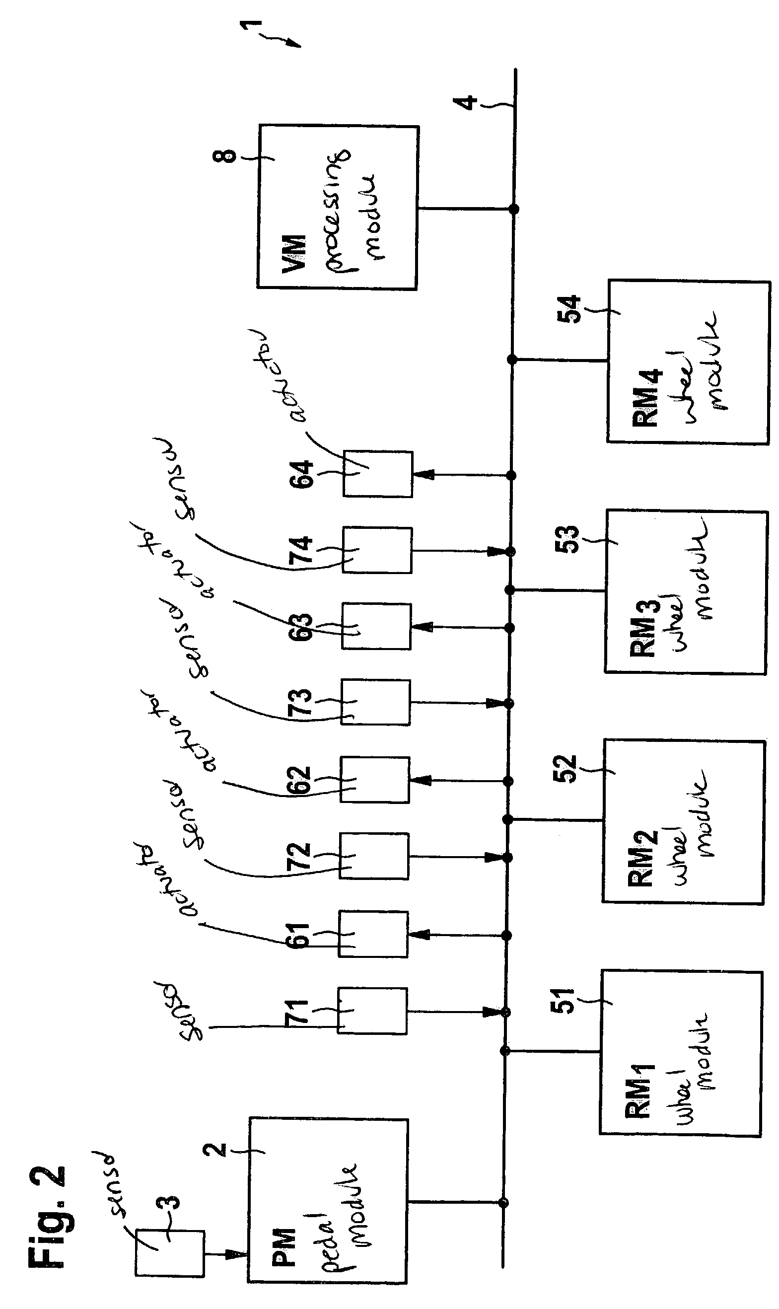
[0038]The structure of the electric computer system according to the present invention is illustrated in FIG. 1 using the example of an electric brake system. Computer system 1 includes a pedal module (PM)2 in which sensors 3 detect the intent of a driver of the vehicle with respect to use of the service brakes and also with respect to use of the parking brake or emergency brake. The driver's intent thus detected is used to calc...


PUM


Abstract

A method of mutual monitoring of components of a distributed computer system for a safety-relevant application in a motor vehicle in particular. The components are interconnected by at least one communication system. To make the mutual monitoring of components as simple and comprehensible as possible and to save on additional hardware components for monitoring, in a plurality of components of the computer system an internal monitoring function which detects faults in the monitored component and a mutual monitoring function which performs a mutual check on results determined by the components and makes a majority selection from the results are implemented, and both the result of the internal monitoring function and the results of the mutual monitoring functions are taken into account in a decision as to whether there is a fault in a component.

Description

FIELD OF THE INVENTION[0001]The present invention relates to a method for mutual monitoring of components of a distributed computer system for a safety-relevant application, in particular in a motor vehicle. The components are interconnected via at least one communication system.[0002]The present invention also relates to a computer program for implementation of mutual monitoring of components of a distributed computer system for a safety-relevant application in a motor vehicle in particular. The computer program here is capable of running on a computing element, in particular on a microprocessor.[0003]The present invention additionally relates to a control unit for a component of a distributed computer system including a plurality of components for a safety-relevant application in a motor vehicle in particular.[0004]Finally, the present invention also relates to a distributed computer system including a plurality of components for a safety-relevant application in a motor vehicle in...

Claims


Application Information

Patent Timeline
Patent Type & Authority Patents(United States)
IPC IPC(8): G06F11/00B60T8/88G06F11/30
CPCB60T8/885G06F11/3006G06F11/3013G06F11/3055G06F11/3082B60T2270/413G05B2219/24033G05B2219/31356Y02P90/02
Inventor HECKMANN, HANSWEIBERLE, REINHARDKESCH, BERNDBLESSING, PETER
Owner ROBERT BOSCH GMBH
Why Eureka
Try Eureka