Combustion liner having improved cooling and sealing

a combustion liner and sealing technology, which is applied in the direction of machines/engines, stators, light and heating equipment, etc., can solve the problems of reducing overall performance and efficiency, allowing no cooling air leakage, and using more air than necessary, so as to improve the cooling effectiveness along the aft end of the combustion liner. , the effect of extending the life of the component and simplifying the geometry of the combustion liner

Active Publication Date: 2007-09-18
ANSALDO ENERGIA SWITZERLAND AG
View PDF6 Cites 34 Cited by
  • Summary
  • Abstract
  • Description
  • Claims
  • Application Information

AI Technical Summary

Benefits of technology

[0007]The present invention seeks to provide a combustion liner having an alternate interface region between it and a transition duct where the cooling effectiveness along the aft end of the combustion liner is improved, resulting in extended component life, while accomplishing this utilizing a simpler combustion liner geometry. The combustion liner comprises a first end, a second end, and is formed from three portions, with the third portion fixed proximate the second end and comprising an inner liner wall, an outer liner wall, a first spring seal adjacent to the outer liner wall, a second spring seal adjacent the first spring seal, and a plurality of cooling holes extending from the outer liner wall to the inner liner wall. Each of the first and second spring seals contain a plurality of axial slots with the slots preferably offset circumferentially. The second spring seal is positioned over the first spring seal to control the amount of cooling air passing through the plurality of first axial slots. Cooling air then passes over the outer liner wall and through the cooling holes, which are preferably angled both axially and circumferentially to maximize the length of the cooling hole, before providing cooling to the inner liner wall.
[0008]It is an object of the present invention to provide a combustion liner having an interface region with a transition duct that has improved cooling effectiveness.
[0009]It is another object of the present invention to provide a simplified geometry for the aft end region of a combustion liner.

Problems solved by technology

However, it is critical to only use the minimal amount of cooling air necessary to lower the operating metal temperatures of combustor 13 to within the acceptable range, and not use more air than necessary nor allow any cooling air leakage.
Seals or tight tolerances between such mating components are typically employed to overcome such leakages that can reduce overall performance and efficiency.

Method used


Image

  • Combustion liner having improved cooling and sealing
  • Combustion liner having improved cooling and sealing
  • Combustion liner having improved cooling and sealing

Examples


Embodiment Construction

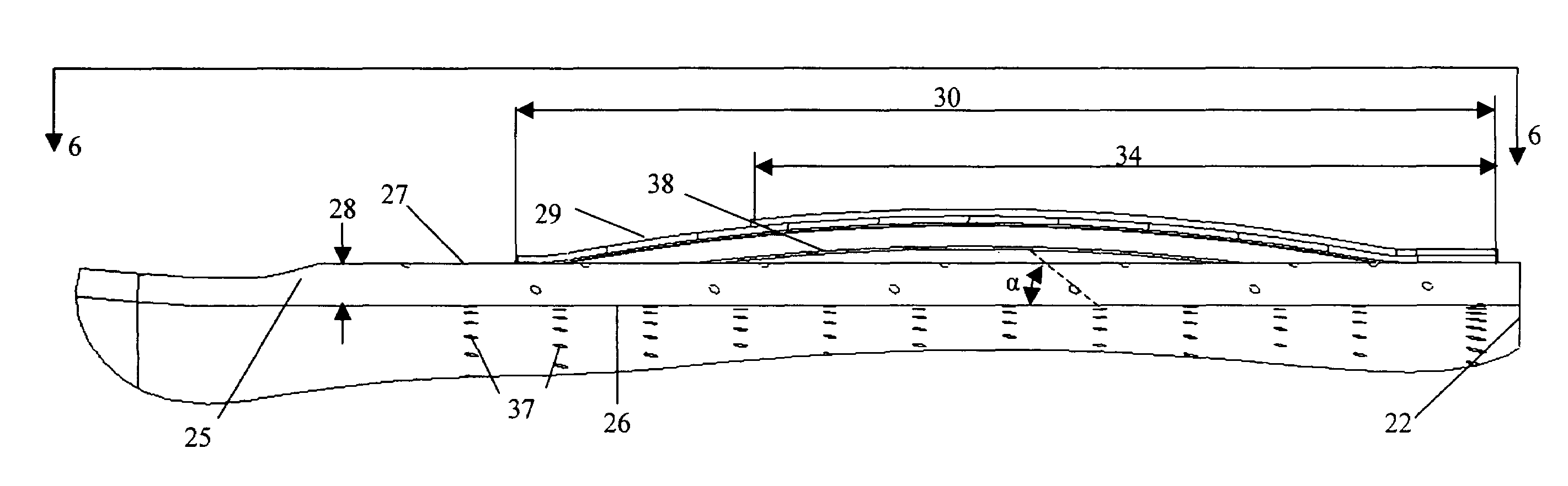
[0017]The preferred embodiment of the present invention is shown in detail in FIGS. 3-6. Referring now to FIG. 3, combustion liner 20 is shown in perspective view with emphasis on its aft region, which interfaces with a transition duct similar to that of transition duct 14 in FIG. 1. Combustion liner 20 comprises a first end 21, a second end 22, and a centerline A-A. Located proximate first end 21 is a first portion 23 that is generally cylindrical in shape. Fixed to first portion 23 and extending towards second end 22 is a second portion 24. Depending on the volume of fuel and air and required flow velocities through combustion liner 20, second portion 24 may be either generally cylindrical or generally conical. FIG. 4 reflects a generally conical shape to second portion 24. A third portion 25 is fixed to second portion 24 opposite first portion 23 and proximate second end 22. Third portion 25 is shown in greater detail in FIG. 5 and comprises an inner liner wall 26 and outer liner...


PUM


Abstract

A gas turbine combustion liner is disclosed having an alternate interface region between it and a transition duct where the cooling effectiveness along the aft end of the combustion liner is improved, resulting in extended component life, while utilizing a simpler combustion liner geometry. The region of the combustion liner proximate its second end comprises a plurality of spring seals that seal against a transition duct while admitting a cooling fluid to pass into a passage, formed between the combustion liner and spring seals, that feeds a plurality of cooling holes located in the combustion liner proximate the liner second end. Depending on the cooling requirements, the cooling holes can be angled both axially and circumferentially to maximize the cooling effectiveness.

Description

TECHNICAL FIELD[0001]This invention relates in general to gas turbine engines and more specifically to the cooling and sealing arrangement of the aft end of a combustion liner.BACKGROUND OF THE INVENTION[0002]A gas turbine engine typically comprises at least one combustor, which mixes air from a compressor with a fuel. This fuel and air mixture combusts after being introduced to an ignition source. The resulting hot combustion gases pass through the combustion system and into a turbine, where the gases turn the turbine and associated shaft. A gas turbine engine is most commonly used for either propulsion for propelling a vehicle or harnessing the rotational energy from the engine shaft to drive a generator for producing electricity. Most land-based gas turbine engines employ a plurality of combustors arranged in a can-annular layout around the engine. Referring to FIG. 1, a representative land based gas turbine engine 10 of the prior art is shown in partial cross section. Gas turbin...

Claims


Application Information

Patent Timeline
Patent Type & Authority Patents(United States)
IPC IPC(8): F23R3/60F01D9/02F23R3/00F23R3/42F23R3/46
CPCF01D9/023F23R3/002F23R3/46Y02T50/675Y02T50/60
Inventor MARTLING, VINCENT C.XIAO, ZHENHUA
Owner ANSALDO ENERGIA SWITZERLAND AG
Why Eureka
Try Eureka