Luggage handle system with pivot grip

a technology of luggage handle and pivot grip, which is applied in the field of rolling luggage handle system, can solve the problems of uncomfortable extended grip, unnecessary cost, and unduly complicated luggage rolling luggage design

Inactive Publication Date: 2007-09-18
TRAVELPRO INT
View PDF22 Cites 17 Cited by
  • Summary
  • Abstract
  • Description
  • Claims
  • Application Information

AI Technical Summary

Benefits of technology

[0010]The gear assembly can include a gear housing having a gear disposed therein. The gear can pivot within the gear housing. The gear housing can include a cylindrical portion, a domed portion, and a bore extending through a length of the gear housing. The domed portion can include a slot through which a stem of the gear extends. The gear can have a rounded base with two substantially flat portions which can engage substantially flat inner walls of the bore of the gear housing thereby facilitating pivotal movement of the gear in a plane that is substantially parallel with the substantially flat portions of the gear. A contour of the slot of the domed portion of the gear housing can serve to limit the pivotal movement of the gear in at least one direction.
[0011]The handle can include a push button plate having a ridge. The stem of the gear can include a plurality of slots joined by a channel that is substantially perpendicular to the plurality of slots. The ridge can ride within the plurality of slots and the channel thereby facilitating rotational motion of the handle. The plurality of slots can include a middle slot and two outer slots. Each outer slot can be separated from the middle slot by about 90 degrees around a circumference of the stem. Accordingly, the handle can rotate approximately 90 degrees in either a clockwise or a counter-clockwise direction about the distal end of the telescoping member(s) according to positions of the outer slots with respect to the middle slot.
[0015]The gear assembly can include a gear housing having a gear disposed therein. The gear can pivot within the gear housing. The gear housing further can include a cylindrical portion, a domed portion, and a bore extending through a length of the gear housing. The domed portion can include a slot through which a stem of the gear extends. The gear can include a rounded base with two substantially flat portions. The substantially flat portions can engage substantially flat inner walls of the bore of the gear housing thereby facilitating pivotal movement of the gear in a plane that is substantially parallel with the substantially flat portions of the gear. A contour of the slot of the domed portion of the gear housing can limit the pivotal movement of the gear in at least one direction.
[0016]The handle can include a push button plate having a ridge. The stem of the gear can include a plurality of slots joined by a channel that is substantially perpendicular to the plurality of slots. The ridge can ride within the plurality of slots and the channel thereby facilitating rotational motion of the handle. The plurality of slots can include a middle slot and two outer slots. Each outer slot can be separated from the middle slot by about 90 degrees around a circumference of the stem. The handle can rotate approximately 90 degrees in either a clockwise or a counter-clockwise direction about the end of the telescoping member(s) according to positions of the outer slots with respect to the middle slot.

Problems solved by technology

Configured in this way, the handle assembly provides a gripping surface that is generally oriented transverse to the rolling direction and can therefore be uncomfortable to grip for extended periods of time.
While such handle systems do provide increased comfort and ease of use for users, the inclusion of two separate mechanisms for operation of the handle can unduly complicate the rolling luggage design and add unnecessary cost.

Method used


Image

  • Luggage handle system with pivot grip
  • Luggage handle system with pivot grip
  • Luggage handle system with pivot grip

Examples


Embodiment Construction

[0026]The present invention relates to a handle system for use with rolling luggage. The various embodiments of the handle system disclosed herein provide users with the ability to ergonomically grip the handle during use. This reduces the strain placed on the user's hand, wrist, and arm. Further, users can more easily maneuver the rolling luggage and navigate walkways when traveling.

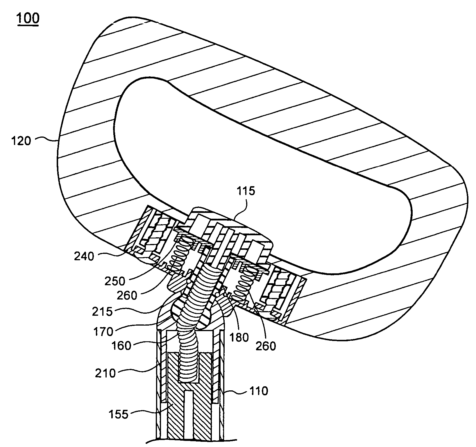
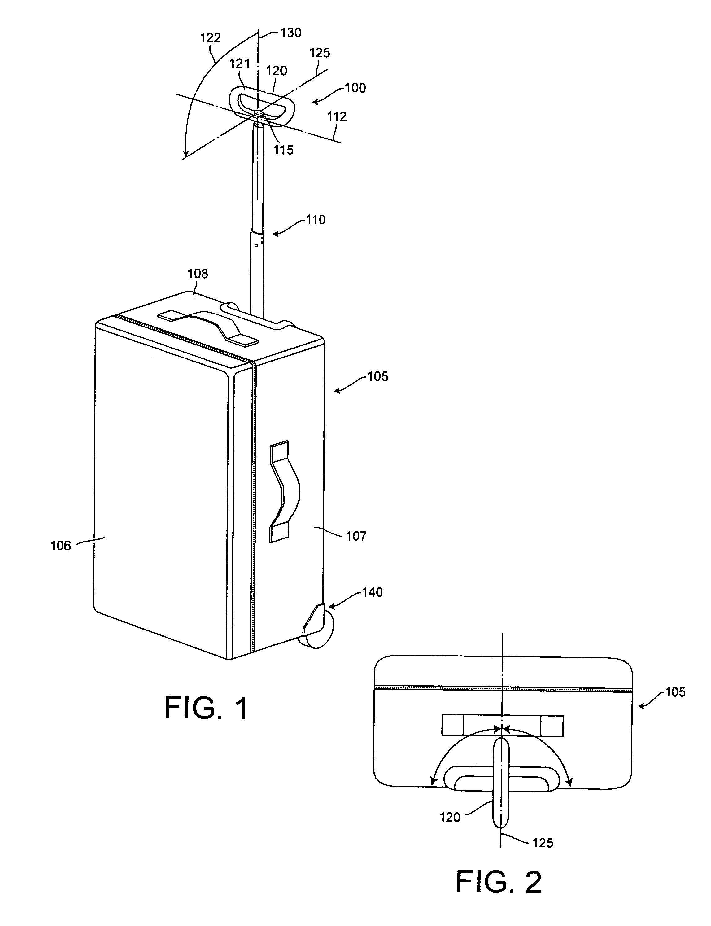
[0027]FIG. 1 is a perspective view of an adjustable handle system 100 attached to a luggage case 105 in accordance with the inventive arrangements disclosed herein. In one embodiment of the present invention, the handle system 100 can include a single telescoping member 110 and a handle 120. The telescoping member 110 can be a post that is extensible from a retracted position within the luggage case 105 to an extended position protruding from the luggage case 105 as shown.

[0028]The luggage case 105 has a top 108, bottom, front 106 and back panels, and a pair of sidewalls 107. Notably, the bottom and bac...


PUM


Abstract

A handle system for a rolling luggage case can include a luggage case in which one or more articles can be stored and having a top, bottom, front, and back panels, and a pair of sidewalls. The luggage case can include a wheel assembly provided at a location on the bottom panel and adjacent to the back panel; at least one telescoping member that is extensible from a retracted position within the luggage case to an extended position protruding from the luggage case; and a gear assembly that is attached to an end of the telescoping member(s) that is distal from the luggage case. The handle system can include a handle attached to the telescoping member(s) through the gear assembly. The gear assembly can provide pivotal and rotational movement of the handle about the end of the telescoping member(s).

Description

BACKGROUND OF THE INVENTION[0001]1. Statement of the Technical Field[0002]The invention generally concerns rolling luggage and, more particularly, a handle system for rolling luggage.[0003]2. Description of the Related Art[0004]Rolling luggage has become increasingly popular in recent years. A common configuration for this type of luggage includes a container or case portion that is generally rectangular in shape in which one or more articles can be stored for travel. The container typically has a top, bottom, front and back panels, and a pair of sidewalls. A wheel assembly is commonly provided to allow the container to be rolled rather than carried. The wheel assembly generally includes a pair of wheels mounted at an interface of the bottom panel and the back panel of the luggage. The orientation of the wheels defines a rolling direction for the luggage that is orthogonal to the axis of rotation for the wheels.[0005]A telescoping handle assembly is generally provided which is attac...

Claims


Application Information

Patent Timeline
Patent Type & Authority Patents(United States)
IPC IPC(8): A45C13/26A45C5/14
CPCA45C13/262A45C2013/265Y10T16/455Y10T16/451A45C2013/267
Inventor MILLER, JACQUELINE N.
Owner TRAVELPRO INT
Why Eureka
Try Eureka