Flood vent

a venting and flood technology, applied in the direction of sash/movable grilles, coastline protection, marine site engineering, etc., to prevent structural damage and limit hydrostatic pressure buildup

Inactive Publication Date: 2007-09-18
ALBANESE ANDREW
View PDF21 Cites 26 Cited by
  • Summary
  • Abstract
  • Description
  • Claims
  • Application Information

AI Technical Summary

Benefits of technology

[0009]The flood vent comprises an elongated box-shaped frame having a top end, a bottom end including a floor, and opposing sidewalls that define a fluid passageway. A door is slidably mounted in the rear of the frame so that a normally closed position blocks the fluid passageway. The door is sufficiently buoyant ...

Problems solved by technology

The device appears to operate more like a storm window than a f...

Method used


Image

  • Flood vent
  • Flood vent
  • Flood vent

Examples


Embodiment Construction

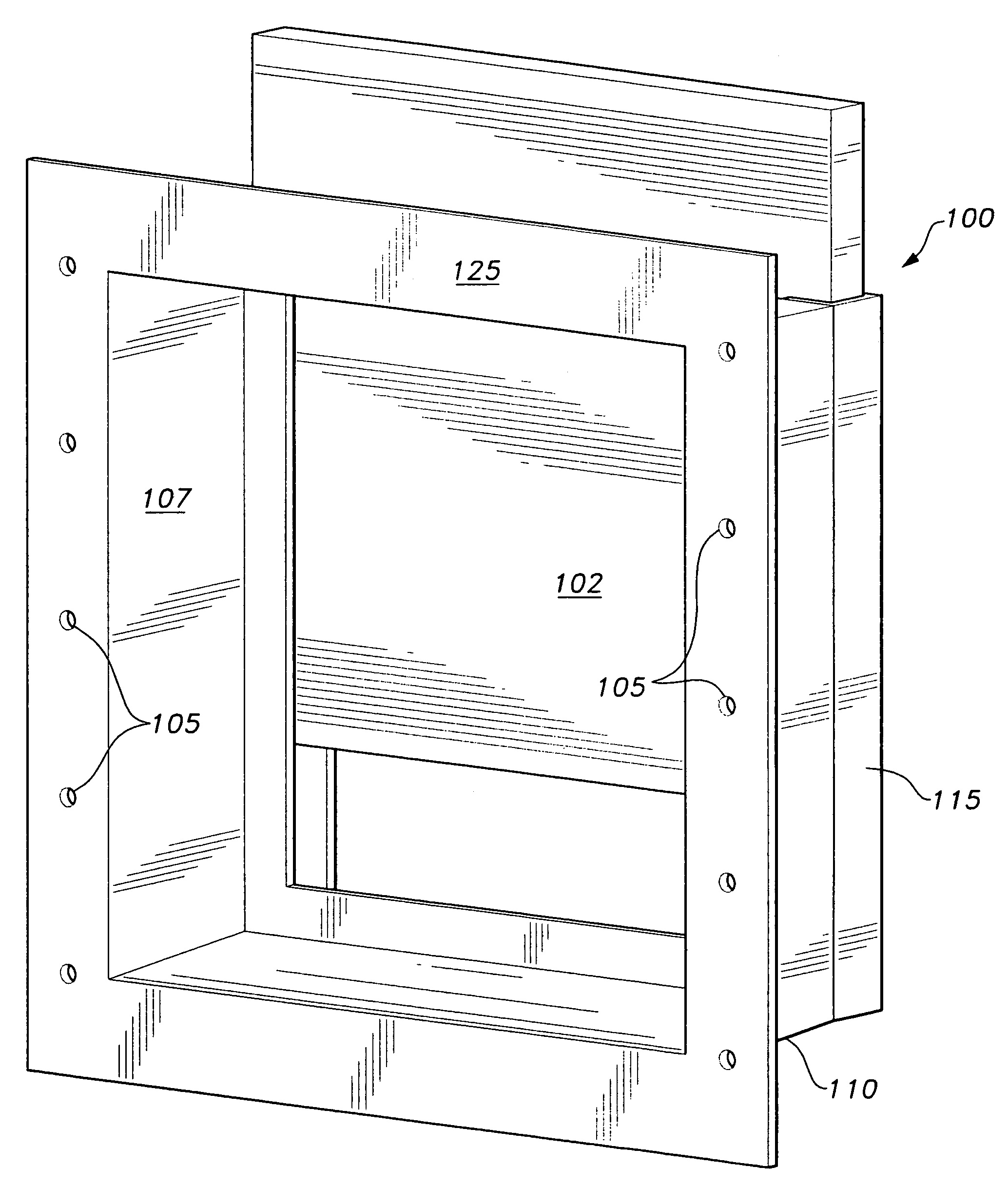
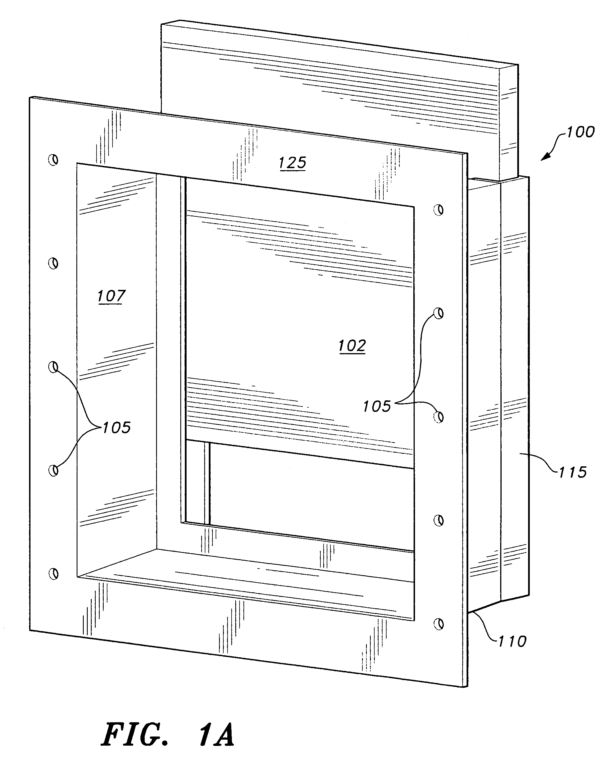
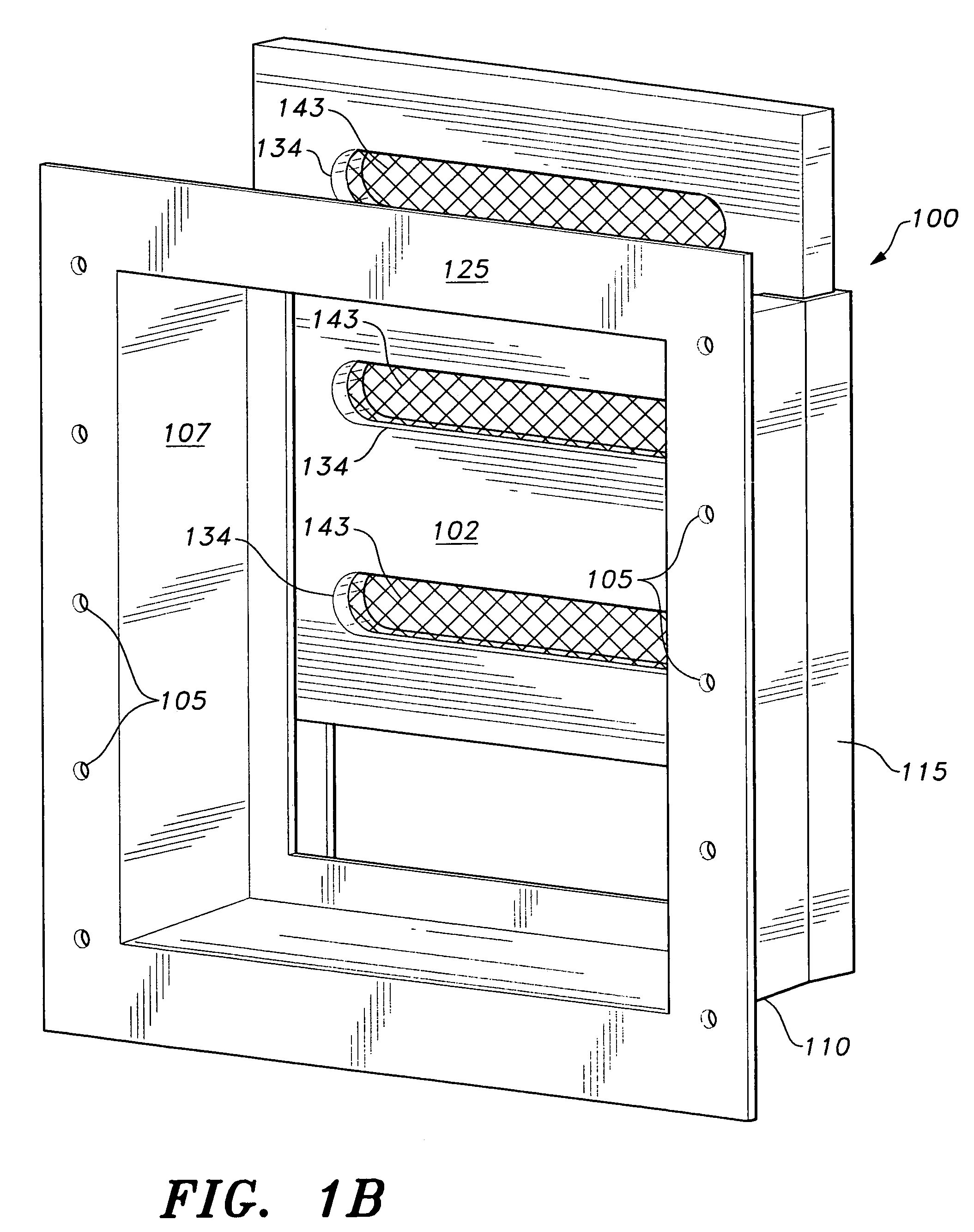
[0015]As shown in FIGS. 1A through 2, the present invention is a flood vent 100 that comprises a box-shaped frame having a top end 111, a bottom end 110, and opposing sidewalls 107 that define a cavity, i.e., a fluid passageway. A door 102 is slidably attached to the rear of the frame so that a normally closed position blocks the fluid passageway. The slidable attachment is formed by vertical flange members 115 being disposed on the rear of the frame laterally. The vertical flange members 115 are U-shaped members that form two vertical channels or tracks within which the door 102 is slidable. The front of the frame is open. The top end 111 of the frame may have a ceiling, or may be open.

[0016]The door 102 is dimensioned so that it can freely slide within, yet is laterally constrained by, the vertical flange members 115. A retaining lip 118 is disposed end-to-end laterally across the bottom 110 of the frame at the rear of the frame. The retaining lip 118 is dimensioned to project rea...


PUM


Abstract

The flood vent has an elongated box-shaped frame having a top end, a bottom end including a floor, and opposing sidewalls that define a fluid passageway. The frame has an open front and a track formed in the rear of the frame. A door is slidably mounted in the track so that a normally closed position blocks the fluid passageway. The door is sufficiently buoyant to permit floodwater to float the door in the track and, thus, to automatically vent excess water through the fluid passageway. Installed in a crawl space, basement, or similar structure, the venting action of the flood vent limits hydrostatic pressure buildup against the walls of the structure when floodwaters rise, thus preventing structural damage from occurring.

Description

CROSS-REFERENCE TO RELATED APPLICATION[0001]This application claims the benefit of U.S. Provisional Patent Application Ser. No. 60 / 812,104, filed Jun. 9, 2006.BACKGROUND OF THE INVENTION[0002]1. Field of the Invention[0003]The present invention relates to crawl space and basement venting, and in particular, to a flood vent that opens to permit the flow of water through a crawl space or foundation level of a building in a flood area when the water level rises in order to avoid excessive hydrostatic pressure against the exterior walls of the structure that might cause the walls to collapse or cave in.[0004]2. Description of the Related Art[0005]To help limit flooding damage, several building code organizations and the federal government have promulgated regulations that mandate that buildings with enclosed spaces located below base flood plain levels, such as crawl spaces, must provide for automatic equalization of interior and exterior hydrostatic forces caused by rising floodwaters....

Claims


Application Information

Patent Timeline
IPC IPC(8): E02B7/26
CPCE04B1/7076E06B9/04E06B2009/007
Inventor ALBANESE, ANDREW
Owner ALBANESE ANDREW
Why Eureka
Try Eureka